Nissan Murano. Manual - part 331


  Главная      Nissan     Nissan Murano (2014 year) - Service Manual


поиск по сайту            


содержание   ..  329  330  331  332   ..


Nissan Murano. Manual - part 331


DEF-20

< DTC/CIRCUIT DIAGNOSIS >

DRIVER SIDE DOOR MIRROR DEFOGGER

Check intermittent incident.
Refer to 

GI-44, "Intermittent Incident"

Is the inspection result normal?

>> INSPECTION END

Component Inspection

INFOID:0000000009722513

1.

CHECK DRIVER SIDE DOOR MIRROR DEFOGGER 

1.

Turn ignition switch OFF.

2.

Disconnect door mirror (driver side) connector.

3.

Check continuity between door mirror terminals.

Is the inspection result normal?

YES

>> INSPECTION END

NO

>> Replace door mirror glass (driver side). Refer to 

MIR-72, "DOOR MIRROR ASSEMBLY : Removal

and Installation"

 (with ADP) or Refer to 

MIR-95, "DOOR MIRROR ASSEMBLY : Removal and

Installation"

 (without ADP).

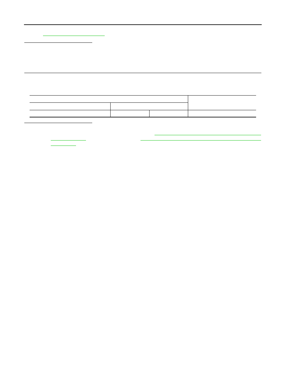
Door mirror (driver side)

Continuity 

 Connector

Terminal 

D3

7

19

Existed

PASSENGER SIDE DOOR MIRROR DEFOGGER

DEF-21

< DTC/CIRCUIT DIAGNOSIS >

C

D

E

F

G

H

I

J

K

M

A

B

DEF

N

O

P

PASSENGER SIDE DOOR MIRROR DEFOGGER

Description

INFOID:0000000009722514

Heats the heating wire with the power supply from the rear window defogger relay to prevent the door mirror
from fogging up.

Component Function Check

INFOID:0000000009722515

1.

CHECK PASSENGER SIDE DOOR MIRROR DEFOGGER

1.

Perform Active Test (“REAR DEFOGGER”) with CONSULT.

2.

Touch “ON”.

3.

Check that the passenger side door mirror glass is getting warmer.

Is the inspection result normal?

YES

>> Passenger side door mirror defogger is OK.

NO

>> Refer to 

DEF-21, "Diagnosis Procedure"

.

Diagnosis Procedure

INFOID:0000000009722516

1.

CHECK POWER SUPPLY CIRCUIT

1.

Turn ignition switch OFF.

2.

Disconnect door mirror (passenger side) connector.

3.

Turn ignition switch ON.

4.

Check voltage between door mirror (passenger side) harness connector and ground.

Is the inspection result normal?

YES

>> GO TO 2.

NO

>> Repair or replace harness or connector between fuse block (J/B) and door mirror (passenger

side).

2.

CHECK GROUND CIRCUIT

1.

Turn ignition switch OFF.

2.

Check continuity between door mirror (passenger side) harness connector and ground.

Is the inspection result normal?

YES

>> GO TO 3.

NO

>> Repair or replace harness or connector between door mirror (passenger side) and ground.

3.

CHECK PASSENGER SIDE DOOR MIRROR DEFOGGER

Check passenger side door mirror defogger.
Refer to 

DEF-22, "Component Inspection"

Is the inspection result normal?

YES

>> GO TO 4.

NO

>> Replace door mirror (passenger side).Refer to 

MIR-72, "DOOR MIRROR ASSEMBLY : Removal

and Installation"

 (with ADP) or Refer to 

MIR-95, "DOOR MIRROR ASSEMBLY : Removal and

Installation"

 (without ADP).

4.

CHECK INTERMITTENT INCIDENT

(+)

(-)

Condition of rear win-

dow defogger switch

Voltage (V)

(Approx.)

Door mirror (Passenger side)

Connector

Terminal

D43

7

Ground

ON

Battery voltage

OFF

0

Door mirror (passenger side)

Ground

Continuity 

Connector

Terminal

D43

19

Existed

DEF-22

< DTC/CIRCUIT DIAGNOSIS >

PASSENGER SIDE DOOR MIRROR DEFOGGER

Check intermittent incident.
Refer to 

GI-44, "Intermittent Incident"

>> INSPECTION END

Component Inspection

INFOID:0000000009722517

1.

CHECK PASSENGER DOOR MIRROR DEFOGGER 

1.

Turn ignition switch OFF.

2.

Disconnect door mirror (passenger side) connector.

3.

Check continuity between door mirror terminals.

Is the inspection result normal?

YES

>> INSPECTION END

NO

>> Replace door mirror glass (passenger side). Refer to 

MIR-72, "DOOR MIRROR ASSEMBLY :

Removal and Installation"

 (with ADP) or Refer to 

MIR-95, "DOOR MIRROR ASSEMBLY :

Removal and Installation"

 (without ADP).

Door mirror (passenger side) 

Continuity 

Connector

Terminal 

D43

7

19

Existed

REAR WINDOW DEFOGGER FEEDBACK SIGNAL

DEF-23

< DTC/CIRCUIT DIAGNOSIS >

C

D

E

F

G

H

I

J

K

M

A

B

DEF

N

O

P

REAR WINDOW DEFOGGER FEEDBACK SIGNAL

WITHOUT BOSE SYSTEM

WITHOUT BOSE SYSTEM : Component Function Check

INFOID:0000000009722518

1.

CHECK REAR WINDOW DEFOGGER FEEDBACK SIGNAL

Check that the indicator lamp of rear window defogger switch is illuminated when turning the rear window
defogger switch ON.
Is the inspection result normal?

YES

>> Rear window defogger feedback signal is OK.

NO

>> Refer to 

DEF-23, "WITHOUT BOSE SYSTEM : Diagnosis Procedure"

.

WITHOUT BOSE SYSTEM : Diagnosis Procedure

INFOID:0000000009722519

1.

CHECK AUTO A/C

Check the operating condition of auto A/C.
Does auto A/C operate normally?

YES

>> GO TO 2.

NO

>> Perform auto A/C diagnosis. Refer to 

HAC-108, "Diagnosis Chart By Symptom"

.

2.

CHECK REAR WINDOW DEFOGGER FEEDBACK SIGNAL CIRCUIT 1

1.

Turn ignition switch ON.

2.

Check voltage between A/C auto amp. harness connector and ground.

Is the inspection result normal?

YES

>> GO TO 3.

NO

>> GO TO 5.

3.

REPLACE A/C CONTROL

1.

Turn ignition switch OFF.

2.

Replace A/C control (rear window defogger switch).

3.

Turn ignition switch ON.

4.

Operate rear window defogger switch and check the operating condition.

Is the inspection result normal?

YES

>> INSPECTION END.

NO

>> GO TO 4.

4.

REPLACE A/C AUTO AMP.

1.

Turn ignition switch OFF.

2.

Replace A/C auto amp.

3.

Turn ignition switch ON.

4.

Operate rear window defogger switch and check the operating condition.

Is the inspection result normal?

YES

>> INSPECTION END.

NO

>> GO TO 7.

5.

CHECK FUSE BLOCK (J/B)

1.

Turn ignition switch OFF.

2.

Disconnect fuse block (J/B) connector.

3.

Turn ignition switch ON.

(+)

(-)

Condition

Voltage (V)

(Approx.)

A/C auto amp.

Connector

Terminal

M50

26

Ground

Rear window defogger 
switch

ON

Battery voltage

OFF

0


содержание   ..  329  330  331  332   ..