содержание .. 267 268 269 270 ..
Nissan Murano. Manual - part 269
CHG-32
< REMOVAL AND INSTALLATION >
ALTERNATOR
REMOVAL AND INSTALLATION
ALTERNATOR
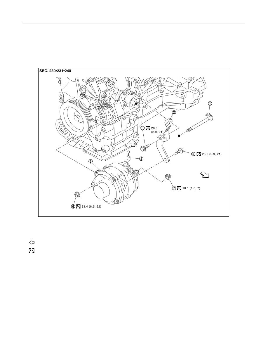
Exploded View
INFOID:0000000009722565
REMOVAL
DISASSEMBLY
1.
Alternator mounting bolt (lower)
2.
Alternator bracket
3.
Alternator bracket mounting bolt
4.
Alternator connector
5.
Alternator
6.
Alternator mounting nut (lower)
7.
“B” terminal nut
8.
Alternator mounting bolt (upper)
: Vehicle front
: N·m (kg-m, ft-lb)
JSMIA1554GB