содержание .. 194 195 196 197 ..
Nissan Murano. Manual - part 196
BCS
BCM (BODY CONTROL MODULE)
BCS-93
< ECU DIAGNOSIS INFORMATION >
C
D
E
F
G
H
I
J
K
L
B
A
O
P
N
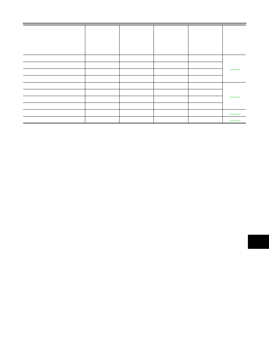
C1708: [NO DATA] FL
—
—
—
×
C1709: [NO DATA] FR
—
—
—
×
C1710: [NO DATA] RR
—
—
—
×
C1711: [NO DATA] RL
—
—
—
×
C1716: [PRESSDATA ERR] FL
—
—
—
×
C1717: [PRESSDATA ERR] FR
—
—
—
×
C1718: [PRESSDATA ERR] RR
—
—
—
×
C1719: [PRESSDATA ERR] RL
—
—
—
×
C1729: VHCL SPEED SIG ERR
—
—
—
×
C1734: CONTROL UNIT
—
—
—
×
CONSULT display
Fail-safe
Freeze Frame
Data
•Vehicle Speed
•Odo/Trip Meter
•Vehicle Condi-
tion
Intelligent Key
warning lamp ON
Tire pressure
monitor warning
lamp ON
Reference