содержание .. 1448 1449 1450 1451 ..
Nissan Murano. Manual - part 1450
WCS-22
< DTC/CIRCUIT DIAGNOSIS >
POWER SUPPLY AND GROUND CIRCUIT
DTC/CIRCUIT DIAGNOSIS
POWER SUPPLY AND GROUND CIRCUIT
COMBINATION METER
COMBINATION METER : Diagnosis Procedure
INFOID:0000000010089121
1.
CHECK FUSE
Check for blown fuses.
Is the inspection result normal?
YES
>> GO TO 2.
NO
>> Be sure to eliminate cause of malfunction before installing new fuse.
2.
CHECK POWER SUPPLY CIRCUIT
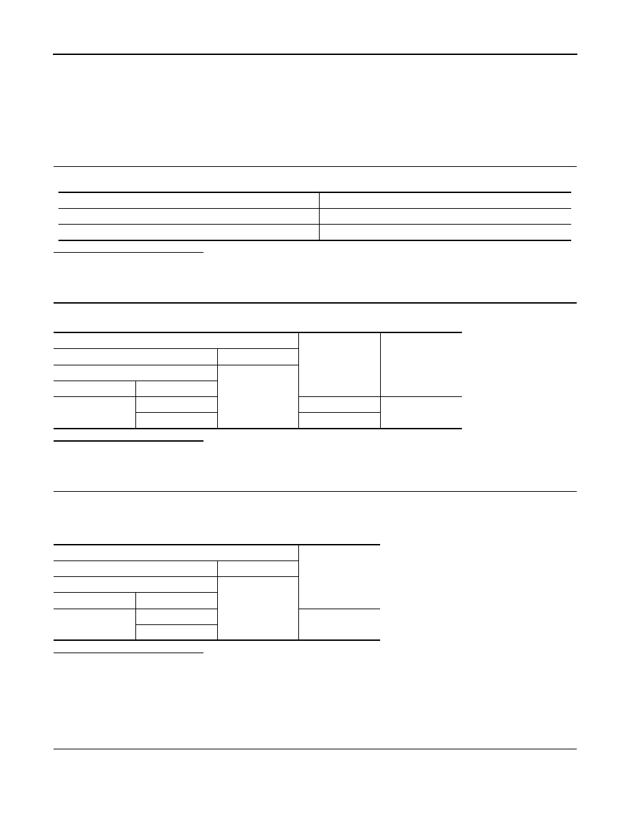
Check voltage between combination meter harness connector terminals and ground.
Is the inspection result normal?
YES
>> GO TO 3.
NO
>> Check harness between combination meter and fuse.
3.
CHECK GROUND CIRCUIT
1.
Turn ignition switch OFF.
2.
Disconnect combination meter connector.
3.
Check continuity between combination meter harness connector terminals and ground.
Is the inspection result normal?
YES
>> INSPECTION END
NO
>> Repair harness or connector.
BCM (BODY CONTROL MODULE)
BCM (BODY CONTROL MODULE) : Diagnosis Procedure
INFOID:0000000010088795
1.
CHECK FUSE AND FUSIBLE LINK
Check that the following fuse and fusible link are not blown.
Power source
Fuse No.
Battery
11
Ignition switch ON or START
4
Terminals
Ignition switch po-
sition
Voltage
(Approx.)
(+)
(-)
Combination meter
Ground
Connector
Terminal
M34
1
OFF
Battery voltage
2
ON
Terminals
Continuity
(+)
(-)
Combination meter
Ground
Connector
Terminal
M34
3
Existed
23