содержание .. 1422 1423 1424 1425 ..
Nissan Murano. Manual - part 1424
VTL-52
< REMOVAL AND INSTALLATION >
[WITHOUT 7 INCH DISPLAY]
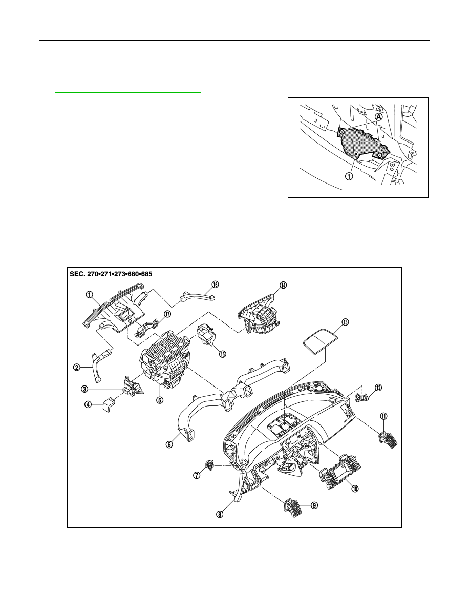
DUCT AND GRILLE
SIDE DEFROSTER GRILLE : Removal and Installation
INFOID:0000000009721113
REMOVAL
1.
Remove defroster nozzle and side defroster nozzle. Refer to
VTL-55, "DEFROSTER NOZZLE AND SIDE
DEFROSTER NOZZLE : Exploded View"
.
2.
Remove fixing screws (A) and then remove side defroster grilles
(left/right) (1).
INSTALLATION
Install in the reverse order of removal.
VENTILATOR DUCT
VENTILATOR DUCT : Exploded View
INFOID:0000000009721114
JPIIA0584ZZ
1.
Defroster nozzle
2.
Side defroster nozzle LH
3.
Foot duct LH
4.
Heater duct
5.
Heater & cooling unit assembly
6.
Ventilator duct
7.
Side defroster grille LH
8.
Instrument panel assembly
9.
Side ventilator grille LH
10. Center ventilator grille assembly
11. Side ventilator grille RH
12. Side defroster grille RH
JPIIA1225ZZ