содержание .. 1275 1276 1277 1278 ..
Nissan Murano. Manual - part 1277
DRIVER AIR BAG MODULE
SR-13
< REMOVAL AND INSTALLATION >
[FOR USA AND CANADA]
C
D
E
F
G
I
J
K
L
M
A
B
SR
N
O
P
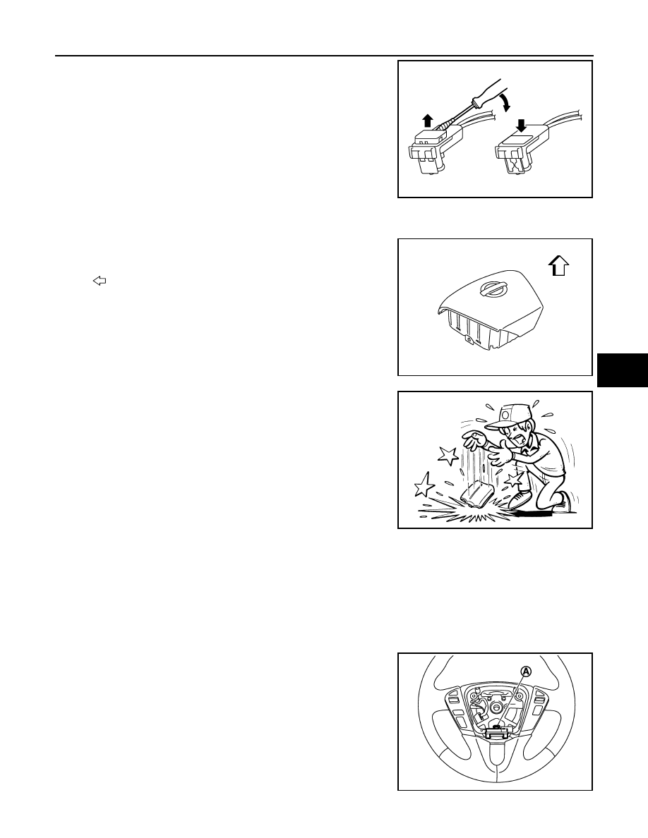
4.
Disconnect the driver air bag harness connector.
CAUTION:
• For installing/removing the driver air bag harness connec-
tor, insert thin screwdriver wrapped in tape into notch, lift
lock and remove the connector.
• Install the connector with lock raised, and push lock into
the connector.
• After installing the connector, check that the lock is
pushed securely into it.
5.
Remove the driver air bag module.
CAUTION:
• Always place the driver air bag module with pad side facing
upward.
• Never impact the driver air bag module.
• Replace the driver air bag module if it has been dropped or
sustained an impact.
• Never insert any foreign objects (screwdriver, etc.) into the driver air bag module.
• Never disassemble the driver air bag module.
• Never expose the driver air bag module to temperatures exceeding 90
°
C (194
°
F).
• Never allow oil, grease, detergent, or water to come in contact with the driver air bag module.
INSTALLATION
Install in the reverse order of removal.
CAUTION:
• Never use the old TORX bolts after removal, replace with the new bolts.
• Fix the driver air bag harness to the harness fixing hook (A).
PHIA0953J
: Upward
JMHIA0504ZZ
JMHIA0009ZZ
JMHIA0505ZZ