Nissan Murano. Manual - part 1242


  Главная      Nissan     Nissan Murano (2014 year) - Service Manual


поиск по сайту            


содержание   ..  1240  1241  1242  1243   ..


Nissan Murano. Manual - part 1242


B2604 SHIFT POSITION

SEC-65

< DTC/CIRCUIT DIAGNOSIS >

[WITH INTELLIGENT KEY SYSTEM]

C

D

E

F

G

H

I

J

L

M

A

B

SEC

N

O

P

3.

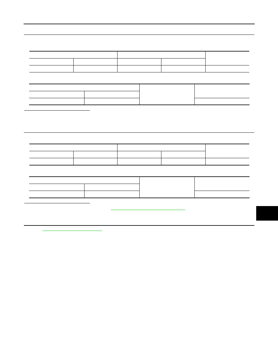
CHECK TRANSMISSION RANGE SWITCH CIRCUIT 2

1.

Disconnect IPDM E/R connector.

2.

Check continuity between IPDM E/R harness connector and BCM harness connector.

3.

Check continuity between IPDM E/R harness connector and ground.

Is the inspection result normal?

YES

>> GO TO 4.

NO

>> Repair or replace harness or connector.

4.

CHECK TRANSMISSION RANGE SWITCH CIRCUIT 3

1.

Check continuity between IPDM E/R harness connector and TCM harness connector.

2.

Check continuity between IPDM E/R harness connector and ground.

Is the inspection result normal?

YES

>> Replace IPDM E/R. Refer to 

PCS-37, "Removal and Installation"

.

NO

>> Repair or replace harness or connector.

5.

CHECK INTERMITTENT INCIDENT

Refer to 

GI-44, "Intermittent Incident"

.

>> INSPECTION END

IPEM E/R

BCM

Continuity

Connector

Terminal

Connector

Terminal

E10

30

M123

140

Existed

IPDM E/R

Ground

Continuity

Connector

Terminal

E10

30

Not existed

IPEM E/R

TCM

Continuity

Connector

Terminal

Connector

Terminal

E10

72

F23

20

Existed

IPDM E/R

Ground

Continuity

Connector

Terminal

E10

72

Not existed

SEC-66

< DTC/CIRCUIT DIAGNOSIS >

[WITH INTELLIGENT KEY SYSTEM]

B2605 SHIFT POSITION

B2605 SHIFT POSITION

Description

INFOID:0000000009722777

BCM confirms the shift position with the following 4 signals.
• CVT shift selector (detention switch)
• Transmission range switch
• P position signal from IPDM E/R (CAN)
• P position signal from TCM (CAN)

DTC Logic

INFOID:0000000009722778

DTC DETECTION LOGIC

NOTE:
• If DTC B2605 is displayed with DTC U1000, first perform the trouble diagnosis for DTC U1000. Refer to

SEC-31, "BCM : DTC Logic"

.

• If DTC B2605 is displayed with DTC U1010, first perform the trouble diagnosis for DTC U1010. Refer to

SEC-33, "BCM : DTC Logic"

.

DTC CONFIRMATION PROCEDURE

1.

PERFORM DTC CONFIRMATION PROCEDURE

1.

Turn ignition switch ON under the following conditions and wait for at least 1 second.

-

Selector lever is in the P or N position

-

Do not depress the brake pedal.

2.

Check “Self diagnostic result” with CONSULT.

Is DTC detected?

YES

>> Go to 

SEC-66, "Diagnosis Procedure"

.

NO

>> INSPECTION END

Diagnosis Procedure

INFOID:0000000009722779

1.

CHECK DTC WITH IPDM E/R

Check “Self diagnostic result” with CONSULT. Refer to 

PCS-34, "DTC Index"

.

Is the inspection result normal?

YES

>> GO TO 2.

NO

>> Repair or replace the malfunctioning parts.

2.

CHECK TRANSMISSION RANGE SWITCH CIRCUIT

1.

Turn ignition switch OFF.

2.

Disconnect TCM connector and BCM connector.

3.

Check continuity between TCM harness connector and BCM harness connector.

4.

Check continuity between TCM harness connector and ground.

DTC No.

Trouble diagnosis 

name

DTC detecting condition

Possible cause

B2605

PNP/CLUTCH SW

BCM detects the following status for 500 ms or 
more when the ignition switch is in ON position
• N position input signal exists. Shift position signal 

from IPDM E/R does not exist.

• N position input signal does not exist. Shift posi-

tion signal from IPDM E/R exists.

• Harness or connectors

(Transmission range switch circuit 
is open or shorted.)

• Transmission range switch
• IPDM E/R

TCM

BCM

Continuity

Connector

Terminal

Connector

Terminal

F23

20

M123

140

Existed

B2605 SHIFT POSITION

SEC-67

< DTC/CIRCUIT DIAGNOSIS >

[WITH INTELLIGENT KEY SYSTEM]

C

D

E

F

G

H

I

J

L

M

A

B

SEC

N

O

P

Is the inspection result normal?

YES

>> GO TO 3.

NO

>> Repair or replace harness or connector.

3.

CHECK INTERMITTENT INCIDENT

Refer to 

GI-44, "Intermittent Incident"

.

>> INSPECTION END

TCM

Ground

Continuity

Connector

Terminal

F23

20

Not existed

SEC-68

< DTC/CIRCUIT DIAGNOSIS >

[WITH INTELLIGENT KEY SYSTEM]

B2608 STARTER RELAY

B2608 STARTER RELAY

Description

INFOID:0000000009722780

Located in IPDM E/R, it runs the starter motor. The starter relay is turned ON by the BCM when the ignition
switch is in START position. IPDM E/R transmits the starter relay ON signal to BCM via CAN communication.

DTC Logic

INFOID:0000000009722781

DTC DETECTION LOGIC

NOTE:
• If DTC B2608 is displayed with DTC U1000, first perform the trouble diagnosis for DTC U1000. Refer to

SEC-31, "BCM : DTC Logic"

.

• If DTC B2608 is displayed with DTC U1010, first perform the trouble diagnosis for DTC U1010. Refer to

SEC-33, "BCM : DTC Logic"

.

• If DTC B2608 is displayed with DTC B210D for IPDM E/R, first perform the trouble diagnosis for DTC

B210D. Refer to 

SEC-81, "DTC Logic"

.

DTC CONFIRMATION PROCEDURE

1.

PERFORM DTC CONFIRMATION PROCEDURE

1.

Turn ignition switch ON under the following conditions.

-

Selector lever is in the P or N position.

-

Do not depress brake pedal.

2.

Check “Self diagnostic result” with CONSULT.

Is DTC detected?

YES

>> Go to 

SEC-68, "Diagnosis Procedure"

.

NO

>> INSPECTION END

Diagnosis Procedure

INFOID:0000000009722782

1.

CHECK BCM POWER SUPPLY CIRCUIT

1.

Turn ignition switch ON.

2.

Check voltage between BCM harness connector and ground.

Is the inspection result normal?

YES

>> GO TO 3.

NO

>> GO TO 2.

2.

CHECK STARTER RELAY CIRCUIT

1.

Turn ignition switch OFF.

2.

Disconnect BCM connector and IPDM E/R connector.

3.

Check continuity between IPDM E/R harness connector and BCM harness connector.

DTC No.

Trouble diagnosis 

name

DTC detecting condition

Possible cause

B2608

STARTER RELAY

BCM receives starter relay ON signal (CAN) from 
IPDM E/R even if BCM turns the starter relay OFF.

• Harness or connectors 

(starter relay circuit is open or 
shorted.)

• IPDM E/R

(+)

(–)

Condition

Voltage (V)

(Approx.)

BCM

Connector

Terminal

M121

52

Ground

Selector lever

N or P position

Battery voltage

Other than above

0


содержание   ..  1240  1241  1242  1243   ..