содержание .. 1226 1227 1228 1229 ..
Nissan Murano. Manual - part 1228
INTELLIGENT KEY SYSTEM/ENGINE START FUNCTION
SEC-9
< SYSTEM DESCRIPTION >
[WITH INTELLIGENT KEY SYSTEM]
C
D
E
F
G
H
I
J
L
M
A
B
SEC
N
O
P
SYSTEM DESCRIPTION
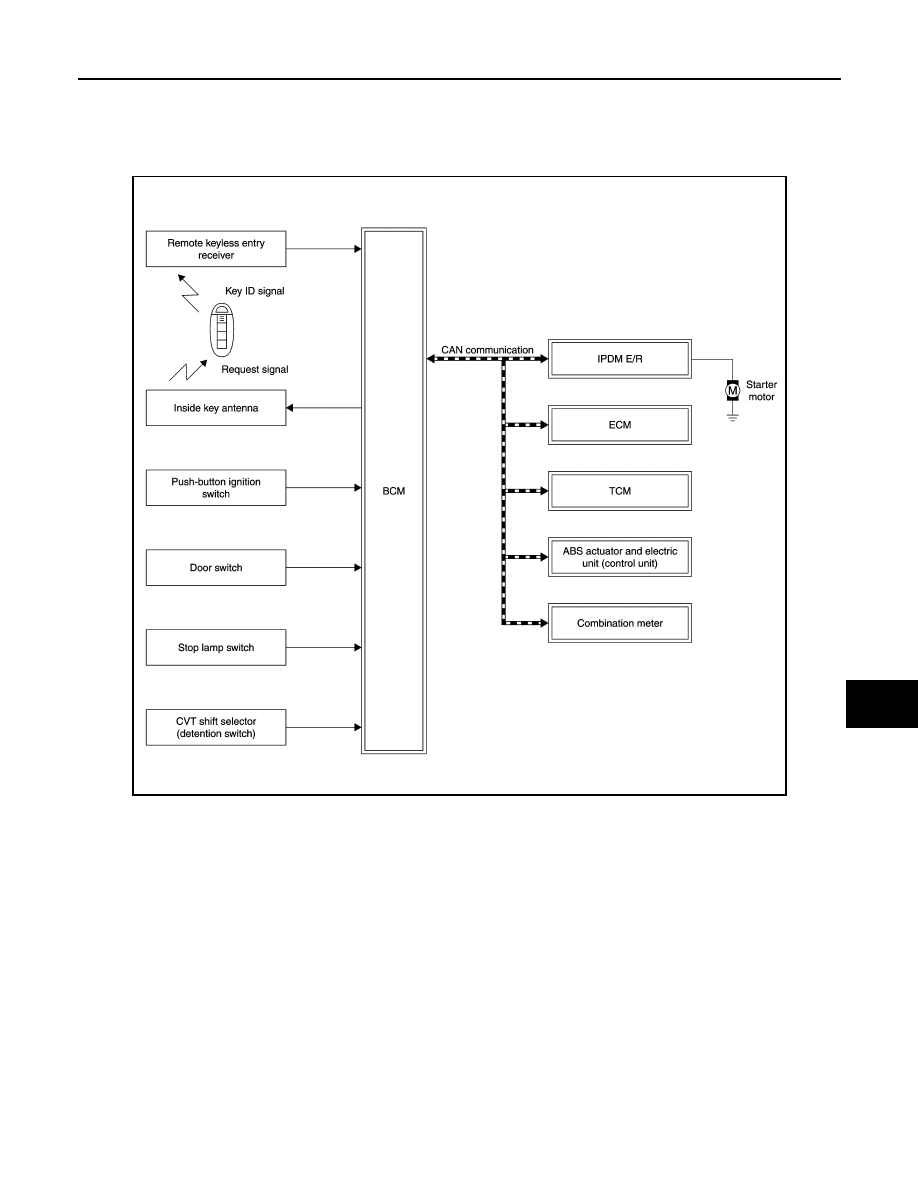
INTELLIGENT KEY SYSTEM/ENGINE START FUNCTION
System Diagram
INFOID:0000000009722696
System Description
INFOID:0000000009722697
SYSTEM DESCRIPTION
• The engine start function of Intelligent Key system is a system that makes it possible to start and stop the
engine without removing the key. It verifies the electronic ID using two-way communications when pressing
the push-button ignition switch while carrying the Intelligent Key, which operates based on the results of
electronic ID verification for Intelligent Key using two-way communications between the Intelligent Key and
the vehicle.
NOTE:
The driver should carry the Intelligent Key at all times.
• Intelligent Key has 2 IDs [for Intelligent Key and for NVIS (NATS)]. It can perform the door lock/unlock oper-
ation and the push-button ignition switch operation when the registered Intelligent Key is carried.
• When the Intelligent Key battery is discharged, it can be used as emergency back-up by inserting the Intelli-
gent Key to the key slot. At that time, the NVIS (NATS) ID verification is performed. If it is used when the
Intelligent Key is carried, the Intelligent Key ID verification is performed.
• If the door lock/unlock operation is performed when the Intelligent Key battery is discharged, all doors lock/
unlock can be performed by operating the driver door key cylinder using the mechanical key set in the Intel-
ligent Key.
JMKIA6548GB