содержание .. 1201 1202 1203 1204 ..
Nissan Murano. Manual - part 1203
POWER RETURN MOTOR
SE-35
< DTC/CIRCUIT DIAGNOSIS >
C
D
E
F
G
H
I
K
L
M
A
B
SE
N
O
P
POWER RETURN MOTOR
LH
LH : Description
INFOID:0000000009718732
Operate the rear seatback.
LH : Component Function Check
INFOID:0000000009718733
1.
CHECK FUNCTION
Check that the rear seatback (LH) rises when pressing and holding the power return switch (LH).
Is the inspection result normal?
YES
>> Power return motor (LH) is OK.
NO
>> Refer to
SE-35, "LH : Diagnosis Procedure"
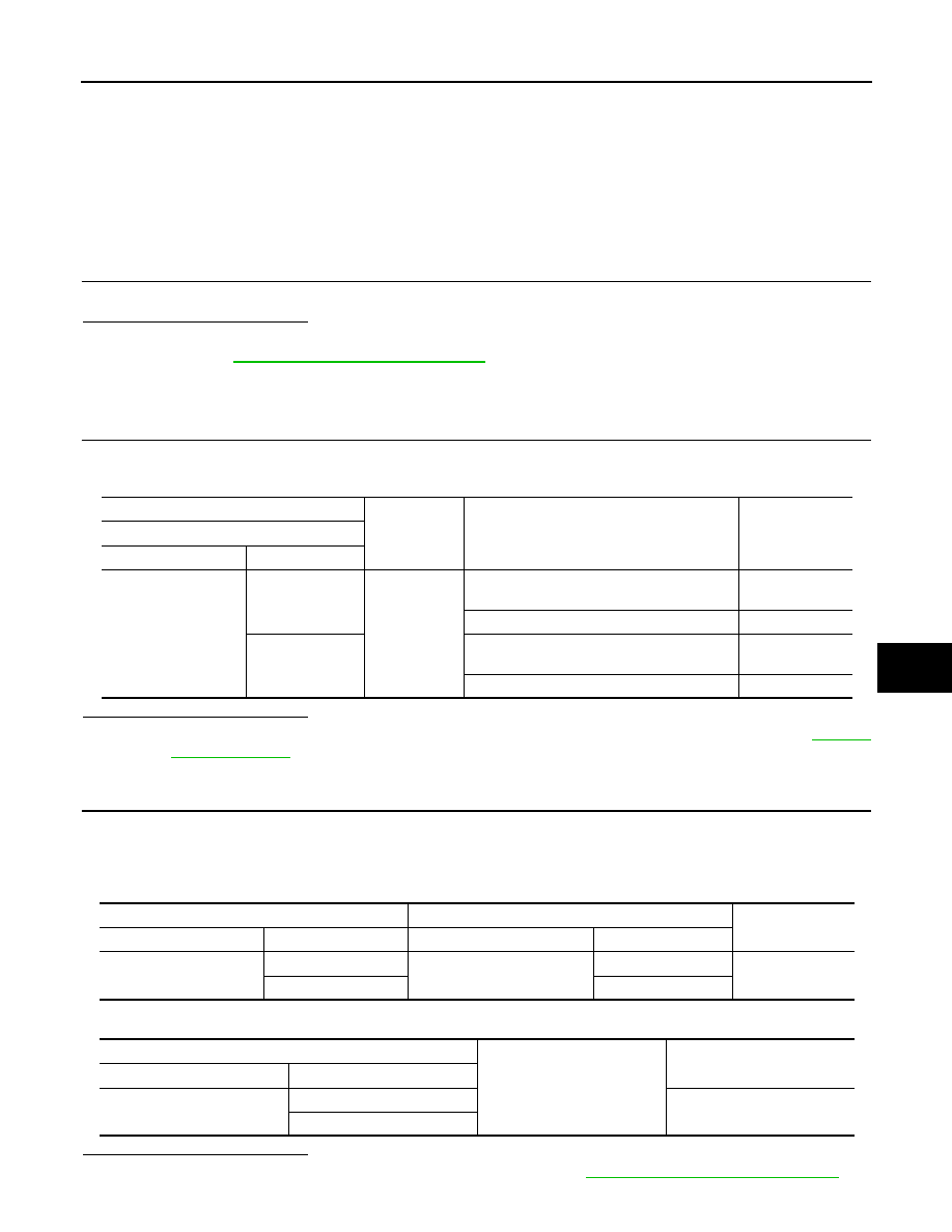
LH : Diagnosis Procedure
INFOID:0000000009718734
1.
CHECK POWER RETURN MOTOR (LH) INPUT SIGNAL
1.
Turn ignition switch OFF.
2.
Check voltage between power return motor assembly (LH) harness connector and ground.
Is the inspection result normal?
YES
>> Replace power return motor assembly (LH) [reclining device assembly (LH)]. Refer to
NO
>> GO TO 2.
2.
CHECK POWER RETURN MOTOR (LH) CIRCUIT
1.
Disconnect rear seatback power return control unit connector and power return motor assembly (LH) con-
nector.
2.
Check continuity between rear seatback power return control unit harness connector and power return
motor assembly (LH) harness connector.
3.
Check continuity between rear seatback power return control unit harness connector and ground.
Is the inspection result normal?
YES
>> Replace rear seatback power return control unit. Refer to
SE-120, "Removal and Installation"
(+)
(–)
Condition
Voltage (V)
(Approx.)
Power return motor assembly (LH)
Connector
Terminal
B498
1
Ground
During the power return motor (LH) return op-
eration
Battery voltage
Other than the above
0
5
During the power return motor (LH) reverse
operation
Battery voltage
Other than the above
0
Rear seatback power return control unit
Power return motor assembly (LH)
Continuity
Connector
Terminal
Connector
Terminal
B492
5
B498
5
Existed
6
1
Rear seatback power return control unit
Ground
Continuity
Connector
Terminal
B492
5
Not existed
6