содержание .. 1156 1157 1158 1159 ..
Nissan Murano. Manual - part 1158
RF-16
< DTC/CIRCUIT DIAGNOSIS >
SUNROOF SWITCH
SUNROOF SWITCH
Description
INFOID:0000000009719657
Transmits switch operation signal to sunroof motor assembly.
Diagnosis Procedure
INFOID:0000000009719658
1.
CHECK SUNROOF SWITCH INPUT SIGNAL
1.
Turn ignition switch ON.
2.
Check voltage between sunroof motor assembly harness connector and ground.
Is the inspection result normal?
YES
>> Replace sunroof motor. Refer to
RF-103, "Removal and Installation"
.
NO
>> GO TO 2.
2.
CHECK SUNROOF SWITCH CIRCUIT
1.
Turn ignition switch OFF.
2.
Disconnect sunroof motor assembly connector and sunroof switch connector.
3.
Check continuity between sunroof motor assembly harness connector and sunroof switch harness con-
nector.
4.
Check continuity between sunroof motor assembly harness connector and ground.
Is the inspection result normal?
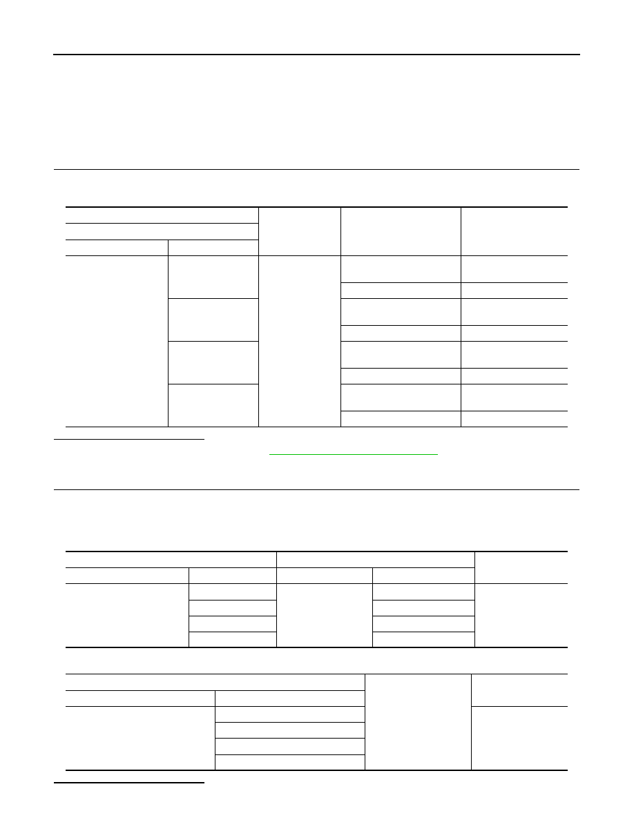
(+)
(–)
Condition
Voltage (V)
(Approx.)
Sunroof motor assembly
Connector
Terminals
R101
4
Ground
Sunroof switch is operated
PUSH
0
Other than above
Battery voltage
5
Sunroof switch is operated
OPEN (1st or 2nd)
0
Other than above
Battery voltage
9
Sunroof switch is operated
OPEN (2nd) or OPEN (2nd)
0
Other than above
Battery voltage
10
Sunroof switch is operated
CLOSE (1st or 2nd)
0
Other than above
Battery voltage
Sunroof motor assembly
Sunroof switch
Continuity
Connector
Terminal
Connector
Terminal
R101
4
R6
5
Existed
5
3
9
2
10
4
Sunroof motor assembly
Ground
Continuity
Connector
Terminal
R101
4
Not existed
5
9
10