Nissan Murano. Manual - part 1120


  Главная      Nissan     Nissan Murano (2014 year) - Service Manual


поиск по сайту            


содержание   ..  1118  1119  1120  1121   ..


Nissan Murano. Manual - part 1120


PWC-18

< DTC/CIRCUIT DIAGNOSIS >

REAR POWER WINDOW SWITCH

REAR POWER WINDOW SWITCH 

Description

INFOID:0000000009723129

Rear power window motor will be operated if rear power window switch is operated.

Component Function Check

INFOID:0000000009723130

1.

 CHECK REAR POWER WINDOW SWITCH FUNCTION

Check rear power window motor operation with rear power window switch.

Is the inspection result normal?

YES

>> Rear power window switch is OK.

NO

>> Refer to 

PWC-18, "Diagnosis Procedure"

.

Diagnosis Procedure

INFOID:0000000009723131

1.

CHECK REAR POWER WINDOW SWITCH INPUT SIGNAL

1.

Turn ignition switch OFF.

2.

Disconnect rear power window switch connector.

3.

Turn ignition switch ON.

4.

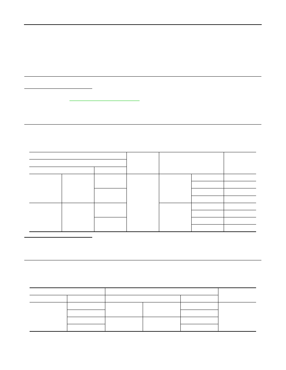
Check voltage between rear power window switch harness connector and ground.

Is the inspection result normal?

YES

>> GO TO 3.

NO

>> GO TO 2.

2.

CHECK REAR POWER WINDOW SWITCH CIRCUIT

1.

Turn ignition switch OFF.

2.

Disconnect power window main switch connector.

3.

Check continuity between power window main switch harness connector and rear power window switch
harness connector.

4.

Check continuity between power window main switch harness connector and ground.

(+)

(–)

Condition

Voltage (V)

(Approx.)

Rear power window switch

Connector

Terminal 

LH

D83

2

Ground

Power window 

main switch: LH

UP

Battery voltage

DOWN

0

3

UP

0

DOWN

Battery voltage

RH

 D103

2

Power window 

main switch: RH

UP

Battery voltage

DOWN

0

3

UP

0

DOWN

Battery voltage

Power window main switch

Rear power window switch

Continuity

Connector

Terminal

Connector

Terminal

D5

1

LH

D83

2

Existed

3

3

5

RH

D103

3

7

2

REAR POWER WINDOW SWITCH

PWC-19

< DTC/CIRCUIT DIAGNOSIS >

C

D

E

F

G

H

I

J

L

M

A

B

PWC

N

O

P

Is the inspection result normal?

YES

>> Replace power window main switch. Refer to 

PWC-118, "Removal and Installation"

.

NO

>> Repair or replace harness.

3.

CHECK REAR POWER WINDOW SWITCH

Check rear power window switch.
Refer to 

PWC-19, "Component Inspection"

.

Is the inspection result normal?

YES

>> GO TO 4.

NO

>> Replace rear power window switch. Refer to 

PWC-118, "Removal and Installation"

.

4.

CHECK INTERMITTENT INCIDENT

Refer to 

GI-44, "Intermittent Incident"

.

>> INSPECTION END

Component Inspection

INFOID:0000000009723132

1.

CHECK REAR POWER WINDOW SWITCH

1.

Turn ignition switch OFF.

2.

Disconnect rear power window switch connector.

3.

Check rear power window switch terminals.

Is the inspection result normal?

YES

>> INSPECTION END

NO

>> Replace rear power window switch. Refer to 

PWC-118, "Removal and Installation"

.

Power window main switch

Ground

Continuity

Connector

Terminal

D5

1

Not existed

3

5

7

Rear power window switch

Terminal

Rear power window switch condi-

tion

Continuity

D83 (LH)

D103 (RH)

1

5

UP

Existed

3

4

3

4

NEUTRAL

2

5

1

4

DOWN

2

5

PWC-20

< DTC/CIRCUIT DIAGNOSIS >

POWER WINDOW MOTOR

POWER WINDOW MOTOR

DRIVER SIDE

DRIVER SIDE : Description

INFOID:0000000009723133

Door glass moves UP/DOWN by receiving the signal from power window main switch.

DRIVER SIDE : Component Function Check

INFOID:0000000009723134

1.

 CHECK FRONT POWER WINDOW MOTOR (DRIVER SIDE) OPERATION

Check front power window motor (driver side) operation with power window main switch.

Is the inspection result normal?

YES

>> Front power window motor (driver side) is OK.

NO

>> Refer to 

PWC-20, "DRIVER SIDE : Diagnosis Procedure"

.

DRIVER SIDE : Diagnosis Procedure

INFOID:0000000009723135

1.

CHECK POWER WINDOW MOTOR (DRIVER SIDE) INPUT SIGNAL

1.

Turn ignition switch OFF.

2.

Disconnect front power window motor (driver side) connector.

3.

Turn ignition switch ON.

4.

Check voltage between power window motor (driver side) harness connector and ground.

Is the inspection result normal?

YES

>> GO TO 3.

NO

>> GO TO 2.

2.

CHECK POWER WINDOW MOTOR CIRCUIT

1.

Turn ignition switch OFF.

2.

Disconnect power window main switch connector.

3.

Check continuity between power window main switch harness connector and front power window motor
(driver side) harness connector.

4.

Check continuity between power window main switch harness connector and ground.

Is the inspection result normal?

YES

>> Replace power window main switch. Refer to 

PWC-118, "Removal and Installation"

.

NO

>> Repair or replace harness.

(+)

(–)

Condition

Voltage (V)

(Approx.)

Power window motor (driver side)

Connector

Terminal

D7

1

Ground

Power window 

main switch

UP

0

DOWN

Battery voltage

2

UP

Battery voltage

DOWN

0

 Power window main switch

Front power window motor (driver side)

Continuity

Connector

Terminal

Connector

Terminal

D5

8

D7

2

Existed

11

1

Power window main switch

Ground

Continuity

Connector

Terminal

D5

8

Not existed

11

POWER WINDOW MOTOR

PWC-21

< DTC/CIRCUIT DIAGNOSIS >

C

D

E

F

G

H

I

J

L

M

A

B

PWC

N

O

P

3.

CHECK FRONT POWER WINDOW MOTOR (DRIVER SIDE)

Check front power window motor (driver side).
Refer to 

PWC-21, "DRIVER SIDE : Component Inspection"

.

Is the inspection result normal?

YES

>> GO TO 4.

NO

>> Replace power window motor (driver side). Refer to 

GW-22, "Removal and Installation"

.

4.

CHECK INTERMITTENT INCIDENT

Refer to 

GI-44, "Intermittent Incident"

.

>> INSPECTION END

DRIVER SIDE : Component Inspection

INFOID:0000000009723136

1.

CHECK FRONT POWER WINDOW MOTOR (DRIVER SIDE)

1.

Turn ignition switch OFF.

2.

Disconnect front power window motor (driver side) connector.

3.

Check motor operate by connecting the battery voltage directly to front power window motor (driver side)
terminals.

Is the inspection result normal?

YES

>> INSPECTION END

NO

>> Replace front power window motor (driver side). Refer to 

GW-22, "Removal and Installation"

.

PASSENGER SIDE

PASSENGER SIDE : Description

INFOID:0000000009723137

Door glass moves UP/DOWN by receiving the signal from power window main switch or front power window
switch (passenger side).

PASSENGER SIDE : Component Function Check

INFOID:0000000009723138

1.

 CHECK FRONT POWER WINDOW MOTOR (PASSENGER SIDE) OPERATION

Check front power window motor (passenger side) operation with power window main switch or front power
window switch (passenger side).
Is the inspection result normal?

YES

>> Power window motor (passenger side) is OK.

NO

>> Refer to 

PWC-21, "PASSENGER SIDE : Diagnosis Procedure"

.

PASSENGER SIDE : Diagnosis Procedure

INFOID:0000000009723139

1.

CHECK FRONT POWER WINDOW MOTOR (PASSENGER SIDE) INPUT SIGNAL

1.

Turn ignition switch OFF.

2.

Disconnect front power window motor (passenger side) connector.

3.

Turn ignition switch ON.

4.

Check voltage between front power window motor (passenger side) harness connector and ground.

Front power window motor (driver side) 

Motor condition

 Connector

Terminal

(+)

(–)

D7

1

2

DOWN

2

1

UP


содержание   ..  1118  1119  1120  1121   ..