содержание .. 1059 1060 1061 1062 ..
Nissan Murano. Manual - part 1061
PCS-6
< SYSTEM DESCRIPTION >
[IPDM E/R]
POWER CONTROL SYSTEM
POWER CONTROL SYSTEM
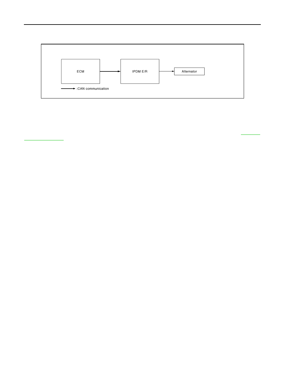
System Diagram
INFOID:0000000009722614
System Description
INFOID:0000000009722615
ALTERNATOR CONTROL
IPDM E/R outputs power generation command signal (PWM signal) to the alternator according to the status of
the power generation command value signal received from ECM via CAN communication. Refer to
.
JPMIA0908GB