Nissan Murano. Manual - part 82


  Главная      Nissan     Nissan Murano (2014 year) - Service Manual


поиск по сайту            


содержание   ..  80  81  82  83   ..


Nissan Murano. Manual - part 82


AV-106

< BASIC INSPECTION >

[BASE AUDIO WITH COLOR DISPLAY]

CONFIGURATION (AV CONTROL UNIT)

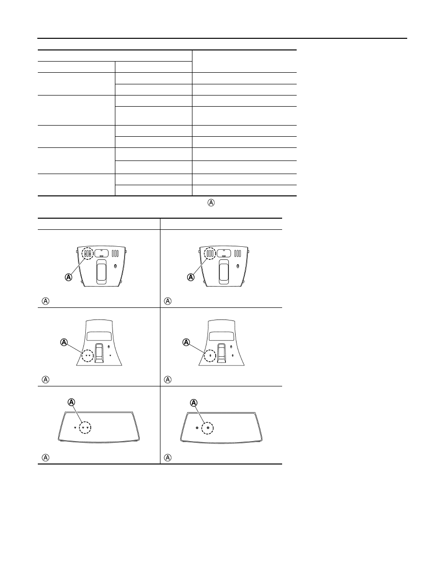
*: In the following table, find an illustration that the 

 part matches the vehicle and select microphone type.

MANUAL SETTING ITEM

Detail

Items

Setting value

STEERING

LHD

LHD models 

RHD

RHD models

CAMERA SYSTEM

REAR CAMERA

With rear view monitor system

REAR+SIDE

With rear view monitor system and 
front-side view monitor function

SOUND SYSTEM

BASE

Without BOSE system

BOSE

With BOSE system

MICROPHONE

DIRECTIONAL MIC

With directional microphone

*

NON-DIRECTIONAL MIC

With non-directional microphone

*

AFFORDABLE ITS

WITH

With BSW and LDW

WITHOUT

Without BSW and LDW

Directional microphone

Non-directional microphone

: Microphone installation position

: Microphone installation position

: Microphone installation position

: Microphone installation position

: Microphone installation position

: Microphone installation position

JSNIA5541ZZ

JSNIA5542ZZ

JSNIA5543ZZ

JSNIA5544ZZ

JSNIA5545ZZ

JSNIA5546ZZ

AV

U1000 CAN COMM CIRCUIT

AV-107

< DTC/CIRCUIT DIAGNOSIS >

[BASE AUDIO WITH COLOR DISPLAY]

C

D

E

F

G

H

I

J

K

L

M

B

A

O

P

DTC/CIRCUIT DIAGNOSIS

U1000 CAN COMM CIRCUIT

Description

INFOID:0000000009721618

CAN (Controller Area Network) is a serial communication line for real-time application. It is an on-vehicle mul-
tiplex communication line with high data communication speed and excellent error detection ability. Many elec-
tronic control units are equipped onto a vehicle, and each control unit shares information and links with other
control units during operation (not independently). In CAN communication, control units are connected with 2
communication lines (CAN-H, CAN-L) allowing a high rate of information transmission with less wiring. Each
control unit transmits/receives data but selectively reads required data only.
CAN Communication Signal Chart. Refer to 

LAN-29, "CAN Communication Signal Chart"

.

DTC Logic

INFOID:0000000009721619

DTC DETECTION LOGIC

Diagnosis Procedure

INFOID:0000000009721620

1.

PERFORM SELF-DIAGNOSTIC

1.

Turn ignition switch ON and wait for 2 seconds or more.

2.

Check “Self Diagnostic Result” of “MULTI AV”. 

Is “CAN COMM CIRCUIT” displayed?

YES

>> Refer to 

LAN-18, "Trouble Diagnosis Procedure"

.

NO

>> Refer to 

GI-44, "Intermittent Incident"

.

DTC

Display contents of CON-

SULT

DTC detection condition

Probable malfunction location

U1000

CAN COMM CIRCUIT
[U1000]

AV control unit is not transmitting or receiving 
CAN communication signal for 2 seconds or 
more.

CAN communication system.

AV-108

< DTC/CIRCUIT DIAGNOSIS >

[BASE AUDIO WITH COLOR DISPLAY]

U1010 CONTROL UNIT (CAN)

U1010 CONTROL UNIT (CAN)

DTC Logic

INFOID:0000000009721621

DTC DETECTION LOGIC

DTC

Display contents of CON-

SULT

DTC detection condition

Probable malfunction factor

U1010

CONTROL UNIT (CAN)
[U1010]

CAN initial diagnosis malfunction is detected.

Replace the AV control unit if the malfunction 
occurs constantly.
Refer to 

AV-149, "Exploded View"

.

AV

U1200 AV CONTROL UNIT

AV-109

< DTC/CIRCUIT DIAGNOSIS >

[BASE AUDIO WITH COLOR DISPLAY]

C

D

E

F

G

H

I

J

K

L

M

B

A

O

P

U1200 AV CONTROL UNIT

DTC Logic

INFOID:0000000009721622

DTC

Display contents of 

CONSULT

DTC detection condition

Possible malfunction factor

U1200

Cont Unit
[U1200]

AV control unit malfunction is detected.

Replace the AV control unit if the mal-
function occurs constantly.
Refer to 

AV-149, "Exploded View"

.


содержание   ..  80  81  82  83   ..