Nissan Murano. Manual - part 73


  Главная      Nissan     Nissan Murano (2014 year) - Service Manual


поиск по сайту            


содержание   ..  71  72  73  74   ..


Nissan Murano. Manual - part 73


AV-70

< ECU DIAGNOSIS INFORMATION >

[BASE AUDIO WITH COLOR DISPLAY]

AV CONTROL UNIT

ECU DIAGNOSIS INFORMATION

AV CONTROL UNIT

Reference Value

INFOID:0000000009721606

VALUES ON THE DIAGNOSIS TOOL

NOTE:
The following table includes information (items) inapplicable to this vehicle. For information (items) applicable
to this vehicle, refer to CONSULT display items.

CONSULT MONITOR ITEM
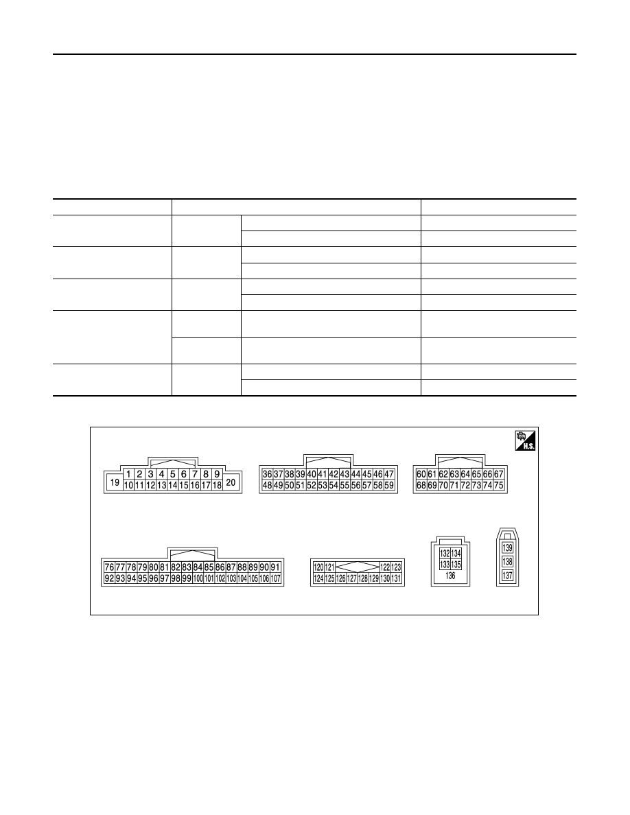
TERMINAL LAYOUT

PHYSICAL VALUES

Monitor Item

Condition

Value/Status

VHCL SPD SIG

Ignition switch 
ON

Vehicle speed > 0 km/h (0 MPH)

On

Vehicle speed = 0 km/h (0 MPH)

Off

PKB SIG

Ignition switch 
ON

Parking brake is applied.

On

Parking brake is released.

Off

ILLUM SIG

Ignition switch 
ON

Lighting switch is ON

On

Lighting switch is OFF

Off

IGN SIG

Ignition switch 
ON

On

Ignition switch 
ACC

Off

REV SIG

Ignition switch 
ON

Selector lever is in R position

On

Selector lever is in any position other than R

Off

JSNIA2831ZZ

AV

AV CONTROL UNIT

AV-71

< ECU DIAGNOSIS INFORMATION >

[BASE AUDIO WITH COLOR DISPLAY]

C

D

E

F

G

H

I

J

K

L

M

B

A

O

P

Terminal

(Wire color)

Description

Condition

Reference value

(Approx.)

+

Signal name

Input/

Output

2

(G)

3

(R)

Sound signal front door 
speaker and front squawk-
er LH

Output

Ignition 

switch 

ON

Sound output

4

(LG)

5

(Y)

Sound signal rear door 
speaker LH

Output

Ignition 

switch 

ON

Sound output

6

(BR)

15

(L)

Steering switch signal A

Input

Ignition 

switch 

ON

Keep pressing SOURCE 
switch.

 0 V

Keep pressing MENU UP 
switch.

0.7 V

Keep pressing MENU 
DOWN switch.

1.3 V

Keep pressing 


switch

2.0 V

Except for above.

3.3 V

7

(R)

Ground

ACC power supply

Input

Ignition 

switch 

ACC

Battery voltage

9

(R)

Ground

Illumination signal

Input

Ignition 

switch 

OFF

Lighting switch is OFF.

0 V

Lighting switch is ON.

12.0 V

11

(W)

12

(L)

Sound signal front door 
speaker and front squawk-
er RH

Output

Ignition 

switch 

ON

Sound output

13

(GR)

14

(P)

Sound signal rear door 
speaker RH

Output

Ignition 

switch 

ON 

Sound output

SKIB3609E

SKIB3609E

SKIB3609E

SKIB3609E

AV-72

< ECU DIAGNOSIS INFORMATION >

[BASE AUDIO WITH COLOR DISPLAY]

AV CONTROL UNIT

16

(G)

15

(L)

Steering switch signal B

Input

Ignition 

switch 

ON

Keep pressing VOL DOWN 
switch.

0 V

Keep pressing VOL UP 
switch.

0.7 V

Keep pressing 

 switch

1.3 V

Except for above.

3.3 V

19

(Y)

Ground

Battery power supply

Input

Ignition 

switch 

OFF

Battery voltage

20

(B)

Ground

Ground

Ignition 

switch 

ON 

0  V

36

(GR)

Ground

Signal VCC

Output

Ignition 

switch 

ACC

9.0  V

37

(SB)

Ground

Signal ground

Ignition 

switch 

OFF

0  V

38

(G)

Ground

Horizontal synchronizing 
(HP) signal

Input

Ignition 

switch 

ON 

39

(L)

Ground

Communication signal
(DISP

CONT)

Input

Ignition 

switch 

ON

When adjusting display 
brightness.

40

(W)

Ground

RGB area (YS) signal

Output

Ignition 

switch 

ON 

At RGB image is displayed.

5.0 V

At AUX image is displayed.

41

Shield

42

(B)

Ground

RGB synchronizing signal

Output

Ignition 

switch 

ON 

Terminal

(Wire color)

Description

Condition

Reference value

(Approx.)

+

Signal name

Input/

Output

SKIB3601E

PKIB5039J

PKIB4948J

SKIB3603E

AV

AV CONTROL UNIT

AV-73

< ECU DIAGNOSIS INFORMATION >

[BASE AUDIO WITH COLOR DISPLAY]

C

D

E

F

G

H

I

J

K

L

M

B

A

O

P

43

(G)

Ground

RGB signal (R: red)

Output

Ignition 

switch 

ON 

Start Confirmation/Adjust-
ment mode, and then dis-

play color bar by selecting 

“Color Spectrum Bar” on 

Display Diagnosis screen.

44

(L)

Ground

RGB signal (G: green)

Output

Ignition 

switch 

ON 

Start Confirmation/Adjust-
ment mode, and then dis-

play color bar by selecting 

“Color Spectrum Bar” on 

Display Diagnosis screen.

45

(Y)

Ground

RGB signal (B: blue)

Output

Ignition 

switch 

ON 

Start Confirmation/Adjust-
ment mode, and then dis-

play color bar by selecting 

“Color Spectrum Bar” on 

Display Diagnosis screen.

46

(V)

Ground

Composite image signal 
ground

Ignition 

switch 

ON

0  V

47

(LG)

Ground

Composite image signal

Output

Ignition 

switch 

ON

At camera image or AUX 
image is displayed.

48

(Y)

Ground

Inverter VCC

Output

Ignition 

switch 

ACC

9.0 V

49

(BR)

Ground

Inverter ground

Ignition 

switch 

OFF

0  V

50

(R)

Ground

Vertical synchronizing (VP) 
signal

Input

Ignition 

switch 

ON 

Terminal

(Wire color)

Description

Condition

Reference value

(Approx.)

+

Signal name

Input/

Output

SKIB2238J

SKIB2236J

SKIB2237J

SKIB2251J

SKIB3598E


содержание   ..  71  72  73  74   ..