Nissan Murano. Manual - part 36


  Главная      Nissan     Nissan Murano (2014 year) - Service Manual


поиск по сайту            


содержание   ..  34  35  36  37   ..


Nissan Murano. Manual - part 36


ADP-136

< ECU DIAGNOSIS INFORMATION >

DRIVER SEAT CONTROL UNIT
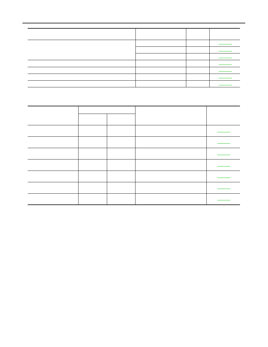
DTC Index

INFOID:0000000009720775

*1

:

• 0: Current malfunction is present

• 1-39: Displayed if any previous malfunction is present when current condition is normal. The numeral value increases by one at each

IGN ON to OFF cycle from 1 to 39. The counter remains at 39 even if the number of cycles exceeds it. However, the counter is reset
to 1 if any malfunction is detected again, the normal operation is resumed and the ignition switch is turned from OFF to ON. 

Operating in

fail-safe mode

Malfunction Item

Related 

DTC

Diagnosis

Only manual functions operate normally.

CAN communication

U1000

ADP-44

CONTROL UNIT

U1010

ADP-45

EEPROM

B2130

ADP-46

Only manual functions, except door mirror, operate normally.

UART communication

B2128

ADP-53

Only manual functions, except seat sliding, operate normally.

Seat sliding output

B2112

ADP-47

Only manual functions, except seat reclining, operate normally.

Seat reclining output

B2113

ADP-49

Only manual functions, except steering tilt, operate normally.

Steering column tilt output

B2116

ADP-51

CONSULT

display

Timing

*1

Item

Reference page

Current mal-

function

Previous mal-

function

CAN COMM CIRCUIT
[U1000]

0

1-39

CAN communication

ADP-44

CONTROL UNIT
[U1010]

0

1-39

Control unit

ADP-45

SEAT SLIDE
[B2112]

0

1-39

Seat slide motor output

ADP-47

SEAT RECLINING
[B2113]

0

1-39

Seat reclining motor output

ADP-49

STEERING TILT
[B2116]

0

1-39

Tilt motor output

ADP-51

UART COMM
[B2128]

0

1-39

UART communication

ADP-53

EEPROM
[B2130]

0

1-39

EEPROM

ADP-46

AUTOMATIC DRIVE POSITIONER CONTROL UNIT

ADP-137

< ECU DIAGNOSIS INFORMATION >

C

D

E

F

G

H

I

K

L

M

A

B

ADP

N

O

P

AUTOMATIC DRIVE POSITIONER CONTROL UNIT

Reference Value

INFOID:0000000009720776

TERMINAL LAYOUT

PHYSICAL VALUES

JMJIA1389ZZ

Terminal No.

(wire color)

Description

Condition

Voltage (V)

(Approx.)

+

-

Signal name

Input/

Output

1

(Y)

Ground

Tilt switch up signal

Input

Tilt switch

Operate
(up)

0

Other than 
above

5

2

(GR)

Ground

Changeover switch RH
signal

Input

Changeover 
switch position

RH

0

Neutral or 
LH

5

3

(SB)

Ground

Mirror switch up signal

Input

Mirror switch

Operated
(up)

0

Other than 
above

5

4

(LG)

Ground

Mirror switch left signal

Input

Mirror switch

Operated
(left)

0

Other than 
above

5

5

(R)

Ground

Door mirror sensor (pas-
senger side) up/down 
signal

Input

Door mirror RH position

Change between 3.4 (close to 

peak) 0.6 (close to valley)

6

(Y)

Ground

Door mirror sensor (driv-
er side) up/down signal

Input

Door mirror LH position

Change between 3.4 (close to 

peak) 0.6 (close to valley)

7

(P)

Ground

Telescopic switch for-
ward signal

Input

Telescopic 
switch

Operate
(forward)

0

Other than 
above

5

8

(LG)

Ground

UART communication 
(TX/RX)

Output

Ignition switch ON

JMJIA1391ZZ

ADP-138

< ECU DIAGNOSIS INFORMATION >

AUTOMATIC DRIVE POSITIONER CONTROL UNIT

10

(GR)

Ground

Door mirror motor (pas-
senger side) up output 
signal

Output

Door mirror RH

Operate
(up)

Battery voltage

Other than 
above

0

11

(G)

Ground

Door mirror motor (pas-
senger side) left output 
signal

Output

Door mirror RH

Operate
(left)

Battery voltage

Other than 
above

0

12

(R)

Ground

Door mirror motor (driv-
er side) down output sig-
nal

Output

Door mirror (LH)

Operate
(down)

Battery voltage

Other than 
above

0

Door mirror motor (driv-
er side) right output sig-
nal

Operate
(right)

Battery voltage

Other than 
above

0

13

(LG)

Ground

Tilt switch down signal

Input

Tilt switch

Operate
(down)

0

Other than 
above

5

14

(BG)

Ground

Changeover switch LH
signal

Input

Changeover 
switch position

LH

0

Neutral or 
RH

5

15

(L)

Ground

Mirror switch down sig-
nal

Input

Mirror switch

Operate
(down)

0

Other than 
above

5

16

(V)

Ground

Mirror switch right signal

Input

Mirror switch

Operate
(right)

0

Other than 
above

5

17

(W)

Ground

Door mirror sensor (pas-
senger side) left/right 
signal

Input

Door mirror RH position

Change between 3.4 (close to left 

edge) 0.6 (close to right edge)

18

(L)

Ground

Door mirror sensor (driv-
er side) left/right signal

Input

Door mirror LH position

Change between 0.6 (close to left 

edge) 3.4 (close to right edge)

19

(G)

Ground

Telescopic switch back-
ward signal

Input

Telescopic 
switch

Operate
(back-
ward)

0

Other than 
above

5

20

(Y)

Ground

Ground

0

21

(W)

Ground

Door mirror motor sen-
sor power supply

Input

Terminal No.

(wire color)

Description

Condition

Voltage (V)

(Approx.)

+

-

Signal name

Input/

Output

AUTOMATIC DRIVE POSITIONER CONTROL UNIT

ADP-139

< ECU DIAGNOSIS INFORMATION >

C

D

E

F

G

H

I

K

L

M

A

B

ADP

N

O

P

22

(V)

Ground

Door mirror motor (pas-
senger side) down out-
put signal

Output

Door mirror (RH)

Operate
(down)

Battery voltage

Other than 
above

0

Door mirror motor (pas-
senger side) right output 
signal

Operate
(right)

Battery voltage

Other than 
above

0

23

(L)

Ground

Door mirror motor (driv-
er side)up output signal

Output

Door mirror (LH)

Operate
(up)

Battery voltage

Other than 
above

0

24

(SB)

Ground

Door mirror motor (driv-
er side)left output signal

Output

Door mirror (LH)

Operate
(left)

Battery voltage

Other than 
above

0

25

(W)

Ground

Power source 

Input

Battery voltage

26

(L)

Ground

Telescopic motor back-
ward output signal

Output

Steering tele-
scopic

Operate
(back-
ward)

Battery voltage

Other than 
above

0

27

(P)

Ground

Tilt&telescopic motor 
power source 

Battery voltage

28

(G)

Ground

Tilt motor down output 
signal

Output

Steering tilt

Operate
(down)

Battery voltage

Other than 
above

0

29

(LG)

Ground

Tilt motor up output sig-
nal

Output

Steering tilt

Operate
(up)

Battery voltage

Other than 
above

0

Telescopic motor for-
ward output signal

Steering tele-
scopic

Operate
(forward)

Battery voltage

Other than 
above

0

30

(B)

Ground

Ground

0

Terminal No.

(wire color)

Description

Condition

Voltage (V)

(Approx.)

+

-

Signal name

Input/

Output


содержание   ..  34  35  36  37   ..