содержание .. 25 26 27 28 ..
Nissan Murano. Manual - part 27
ADP-100
< DTC/CIRCUIT DIAGNOSIS >
MIRROR SENSOR
Is the indication normal?
YES
>> INSPECTION END
NO
>> Perform diagnosis procedure. Refer to
ADP-100, "PASSENGER SIDE : Diagnosis Procedure"
.
PASSENGER SIDE : Diagnosis Procedure
INFOID:0000000009720746
1.
CHECK DOOR MIRROR SENSOR (PASSENGER SIDE) POWER SUPPLY
1.
Turn ignition switch OFF.
2.
Disconnect door mirror (passenger side) connector.
3.
Turn ignition switch ON.
4.
Check voltage between door mirror (passenger side) harness connector and ground.
Is the inspection result normal?
YES
>> GO TO 3.
NO
>> GO TO 2.
2.
CHECK DOOR MIRROR (PASSENGER SIDE) SENSOR POWER SUPPLY CIRCUIT
1.
Turn ignition switch OFF.
2.
Disconnect automatic drive positioner control unit connector.
3.
Check continuity between automatic drive positioner control unit harness connector and door mirror (pas-
senger side) harness connector.
4.
Check continuity between automatic drive positioner control unit harness connector and ground.
Is the inspection result normal?
YES
>> Replace automatic drive positioner control unit. Refer to
ADP-211, "Removal and Installation"
.
NO
>> Repair or replace harness or connector.
3.
CHECK DOOR MIRROR (PASSENGER SIDE) SENSOR GROUND
1.
Turn ignition switch OFF.
2.
Disconnect automatic drive positioner control unit connector.
3.
Check continuity between automatic drive positioner control unit harness connector and door mirror (pas-
senger side) connector.
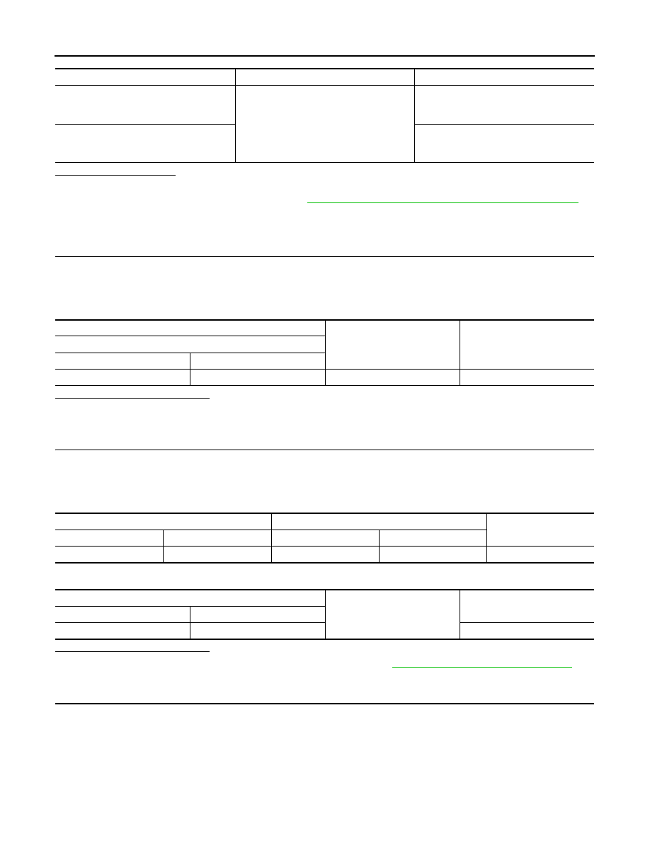
Monitor item
Condition
Value
MIR/SEN RH U-D
Door mirror (passenger side)
Change between
3.4 [V] (close to peak)
0.6 [V] (close to valley)
MIR/SEN RH R-L
Change between
3.4 [V] (close to left edge)
0.6 [V] (close to right edge)
(+)
(–)
Voltage (V)
(Approx.)
Door mirror (passenger side)
Connector
Terminals
D43
23
Ground
5
Automatic drive positioner control unit
Door mirror (passenger side)
Continuity
Connector
Terminal
Connector
Terminal
M75
21
D43
23
Existed
Automatic drive positioner control unit
Ground
Continuity
Connector
Terminal
M75
21
Not existed