содержание .. 973 974 975 976 ..
Nissan X-Trail 32. Manual - part 975
P025A FUEL PUMP
EC-1029
< DTC/CIRCUIT DIAGNOSIS >
[R9M]
C
D
E
F
G
H
I
J
K
L
M
A
EC
N
P
O
3.
CHECK FUEL PUMP RELAY CIRCUIT-II
1.
Disconnect ECM harness connector.
2.
Disconnect IPDM E/R harness connector.
3.
Check the continuity between ECM harness connector and IPDM E/R harness connector.
4.
Also check harness for short to ground and short to power.
Is the inspection result normal?
YES
>> GO TO 4.
NO
>> Repair or replace error-detected parts.
4.
CHECK 20A FUSE
1.
Disconnect 20A fuse (No. 61) from IPDM E/R.
2.
Check 20A fuse.
Is the inspection result normal?
YES
>> INSPECTION END
NO
>> Replace 20A fuse.
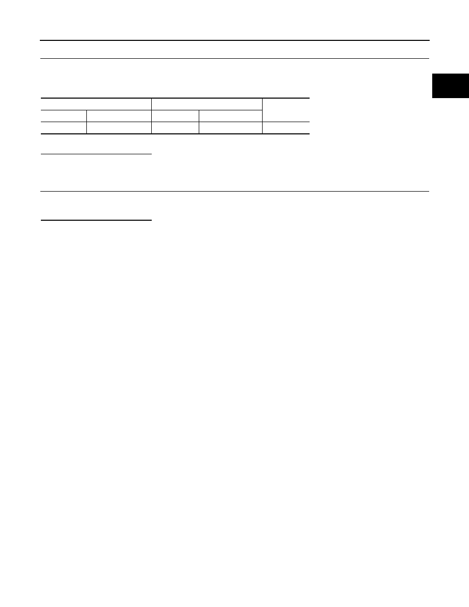
ECM
IPDM E/R
Continuity
Connector
Terminal
Connector
Terminal
F117
38
F72
76
Existed