содержание .. 956 957 958 959 ..
Nissan X-Trail 32. Manual - part 958
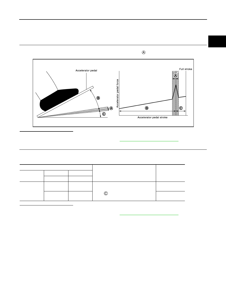
ACCELERATOR PEDAL
EC-961
< BASIC INSPECTION >
[R9M]
C
D
E
F
G
H
I
J
K
L
M
A
EC
N
P
O
ACCELERATOR PEDAL
Work Procedure
INFOID:0000000010935621
1.
PERFORM ACCELERATOR PEDAL FORCE-I
1.
Turn ignition switch OFF.
2.
Depress the accelerator pedal and check if there is a specific point
in the pedal stroke where the pedal
force increase as shown in the figure.
Is the inspection result normal?
YES-1 >> GO TO 2.
NO
>> Replace accelerator pedal assembly. Refer to
ACC-4, "Removal and Installation"
2.
PERFORM ACCELERATOR PEDAL FORCE-II
1.
Turn ignition switch ON.
2.
Check the voltage between ECM harness connector and ground under the following conditions.
Is the inspection result normal?
YES
>> INSPECTION END
NO
>> Replace accelerator pedal assembly. Refer to
ACC-4, "Removal and Installation"
JMBIA1519GB
ECM
Condition
Voltage
Connector
+
–
Terminal
Terminal
E79
2
(APP sensor 1)
3
Depressing range of the accelerator pedal:
Within
as indicated in the figure
More than 4.35 V
11
(APP sensor 2)
12
More than 2.17 V