Nissan X-Trail 32. Manual - part 953


  Главная      Nissan     Nissan X-Trail 32 - Service Manual


поиск по сайту            


содержание   ..  951  952  953  954   ..


Nissan X-Trail 32. Manual - part 953


DIAGNOSIS AND REPAIR WORKFLOW

EC-941

< BASIC INSPECTION >

[R9M]

C

D

E

F

G

H

I

J

K

L

M

A

EC

N

P

O

>> GO TO 8.

8.

DETECT MALFUNCTIONING PART BY DIAGNOSIS PROCEDURE

Inspect according to Diagnosis Procedure of the system.
NOTE:
The Diagnosis Procedure in EC section described based on open circuit inspection. A short circuit inspection
is also required for the circuit check in the Diagnosis Procedure. For details, refer to 

GI-46, "Circuit Inspec-

tion"

.

Is malfunctioning part detected?

YES

>> GO TO 9.

NO

>> Monitor input data from related sensors or check voltage of related ECM terminals using CON-

SULT. Refer to 

EC-889, "Reference Value"

.

9.

REPAIR OR REPLACE THE MALFUNCTIONING PART

1.

Repair or replace the malfunctioning part.

2.

Reconnect parts or connectors disconnected during Diagnosis Procedure again after repair and replace-
ment.

3.

Check DTC. If DTC is displayed, erase it. Refer to 

EC-873, "Diagnosis Description"

.

>> GO TO 10.

10.

FINAL CHECK

When DTC was detected in step 2, perform DTC CONFIRMATION PROCEDURE or Component Function
Check again, and then make sure that the malfunction have been repaired securely.
When symptom was described from the customer, refer to confirmed symptom in step 3 or 4, and make sure
that the symptom is not detected.

Is DTC detected and does symptom remain?

YES-1 >> DTC is detected: GO TO 8.
YES-2 >> Symptom remains: GO TO 6.
NO

>> Before returning the vehicle to the customer, make sure to erase unnecessary DTC in ECM.

Diagnostic Work Sheet

INFOID:0000000010935595

DESCRIPTION

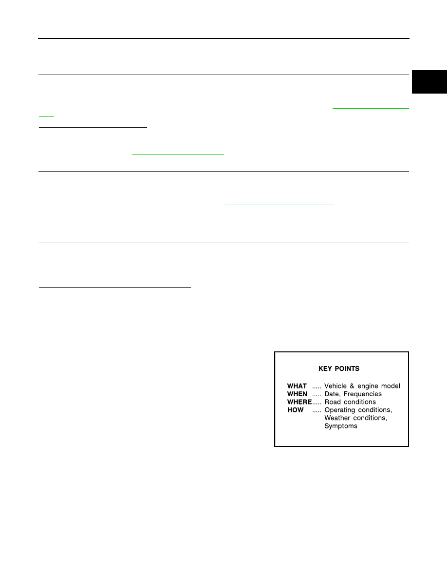
There are many operating conditions that lead to the malfunction of
engine components. A good grasp of such conditions can make trou-
bleshooting faster and more accurate.
In general, each customer feels differently about a incident. It is
important to fully understand the symptoms or conditions for a cus-
tomer complaint.
Utilize a diagnostic worksheet like the one on the next page in order
to organize all the information for troubleshooting.
Some conditions may cause the MIL to come on steady and DTC to
be detected. Examples:
• Vehicle ran out of fuel, which caused the engine to misfire.
• Fuel filler cap was left off or incorrectly screwed on, allowing fuel to

evaporate into the atmosphere.

SEF907L

EC-942

< BASIC INSPECTION >

[R9M]

DIAGNOSIS AND REPAIR WORKFLOW

WORKSHEET SAMPLE

MTBL0017

SERVICE AFTER REPLACING OR REMOVING ENGINE PARTS

EC-943

< BASIC INSPECTION >

[R9M]

C

D

E

F

G

H

I

J

K

L

M

A

EC

N

P

O

SERVICE AFTER REPLACING OR REMOVING ENGINE PARTS

Special Repair Requirement List

INFOID:0000000010935596

×

:Applicable

*1:Harness connector disconnection included.

Part name

Service performed

Required service

Reference

Replace-

ment

Removal

*1

ECM

×

Additional service when replacing ECM

EC-944

Fuel injector

×

Injector adjustment value registration

EC-947

Electric throttle control actuator

×

×

Throttle valve position learning

EC-949

Exhaust electric throttle control 
actuator

×

×

Exhaust throttle valve position learning

EC-950

High pressure EGR volume con-
trol valve

×

×

High pressure EGR volume control valve position 
learning

EC-951

Low pressure EGR volume con-
trol valve

×

×

Low pressure EGR volume control valve position 
learning

EC-952

Intake manifold runner control 
valve

×

×

Intake manifold runner control valve position learn-
ing

EC-953

DPF (Diesel Particulate Filter)

×

DPF (Diesel Particulate Filter) data clear

EC-957

High pressure fuel pump

×

Fuel pump learning value clearing

EC-958

Starter motor

×

Starter motor operating counter clear

EC-960

Engine oil

×

Oil change remaining distance reset 

EC-959

EC-944

< BASIC INSPECTION >

[R9M]

ADDITIONAL SERVICE WHEN REPLACING ECM

ADDITIONAL SERVICE WHEN REPLACING ECM

Description

INFOID:0000000010935597

When replacing ECM, this procedure must be performed.
NOTE:
The necessary operation is different depending on the operation result of ECM data save or write. Always per-
form the operation according to procedures. Refer to 

EC-944, "Work Procedure"

.

Work Procedure

INFOID:0000000010935598

1.

SAVE ECM DATA

1.

Turn ignition switch OFF and wait at least 1 minute.

2.

Reconnect all harness connectors disconnected.

3.

Turn ignition switch ON.

4.

Select “SAVE COMPUTER DATA” in “WORK SUPPORT” mode of “ENGINE” using CONSULT.

5.

Follow the instruction of CONSULT display.
NOTE:
Necessary data in ECM is copied and saved to CONSULT.

Is operation completed successfully?

YES

>> GO TO 2.

NO

>> GO TO 7.

2.

REPLACE ECM

1.

Turn ignition switch OFF and wait at least 1 minute.

2.

Replace ECM. Refer to 

EC-1226, "Removal and Installation"

.

>> GO TO 3.

3.

PERFORM PROGRAMMING

Refer to “CONSULT Operation Manual”.

>> GO TO 4.

4.

PERFORM ECM KEY ID REGISTRATION

Refer to “CONSULT Operation Manual NATS-IVIS/NVIS”.

>> GO TO 5.

5.

PERFORM CONFIGURATION REGISTRATION

1.

Turn ignition switch OFF and wait at least 1 minute.

2.

Turn ignition switch ON.

3.

Check that the battery voltage is between 11 V and 14 V.

4.

Wait at least 10 seconds.

CAUTION:

During this step, never perform any vehicle operation.

5.

If necessary, perform configuration registration using CONSULT function.

>> GO TO 6.

6.

WRITE ECM DATA

1.

Select “WRITE SAVED DATA” in “WORK SUPPORT” mode of “ENGINE” using CONSULT.

2.

Follow the instruction of CONSULT display.
NOTE:
The data saved by “WRITE SAVED DATA” is written to ECM.

Is operation completed successfully?

YES

>> GO TO 12.

NO

>> GO TO 10.


содержание   ..  951  952  953  954   ..