Nissan X-Trail 32. Manual - part 926


  Главная      Nissan     Nissan X-Trail 32 - Service Manual


поиск по сайту            


содержание   ..  924  925  926  927   ..


Nissan X-Trail 32. Manual - part 926


SYSTEM

EC-833

< SYSTEM DESCRIPTION >

[R9M]

C

D

E

F

G

H

I

J

K

L

M

A

EC

N

P

O

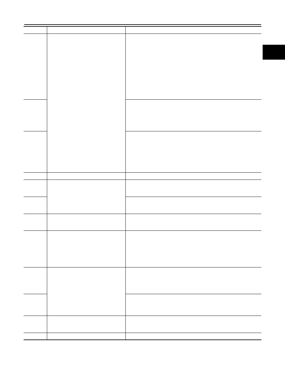
P0641

Sensor power supply

• EGR valve is closed position
• Throttle control motor is opened
• The pressure downstream turbo exists then the limit: Otherwise cut regu-

lation turbo

• Limited upstream turbine pressure regulation if the sensor is present: Oth-

erwise, the boost pressure regulation is cut

• Torque limitation
• Airflow regulation cut off
• CSF regeneration forbidden
• CCSL deactivation with dashboard message
• Freeshift inhibited
• Increased idle speed
• After sales routines forbidden

P0651

• Air conditioner deactivation
• Torque limitation
• CCSL deactivation with dashboard message
• Freeshift inhibited
• After sales routines forbidden
• FAN 2 activation

P0697

• EGR valve is closed position
• Throttle control motor is opened
• Rail pressure limitation
• CSF regeneration forbidden
• After sales routines forbidden
• CCSL deactivation with dashboard message
• Freeshift inhibited
• ESP deactivated and AGB in limp home mode

P0833

DPF pressure sensor

CC/SL not available

P1010
P1012
P1013

Intake manifold runner control valve

Stop intake manifold runner control valve control (Fully open position)

P1011

• Stop intake manifold runner control valve control (Fully open position)
• CCSL deactivation
• Freeshift inhibition

P1453

DPF pressure sensor

• EGR valve is closed position
• Throttle control motor is opened
• Prohibit DPF regeneration

P1480
P1481
P1482
P1483

Exhaust electric throttle control actuator

• EGR valve is closed position
• Throttle control motor is opened
• Airflow regulation cut off
• CSF regeneration forbidden
• Compression test routine forbidden
• CCSL deactivation with dashboard message
• Freeshift inhibited

P1484
P1485
P1486
P1487
P1488

Low pressure EGR volume control valve

• EGR valve is closed position
• Throttle control motor is opened
• CSF regenerations forbidden
• CCSL deactivation with dashboard message
• Freeshift inhibited

P1489

• EGR valve is closed position
• Throttle control motor is opened
• Temperature sensor after EGR cooler overheat signal diagnostic set of 

data to call the failure manag.

P1544

Exhaust gas temperature sensor 2 circuit

• EGR valve is closed position
• Throttle control motor is opened
• Prohibit DPF regeneration

P1620

ECM

Stop closed-loop control

DTC No.

Detected items

Engine operating condition in fail-safe mode

EC-834

< SYSTEM DESCRIPTION >

[R9M]

SYSTEM

STOP/START SYSTEM

ENGINE SPEED CONTROL

P1641
P1642
P1643

Thermoplunger circuit

Stop thermoplunger control

P2002

Diesel particulate filter

• EGR valve is closed position
• Throttle control motor is opened
• Prohibit DPF regeneration

P2120

Accelerator pedal position sensor 2 circuit

• Torque limitation
• Freeshift inhibited
• CCSL deactivation (considered as abnormal with dashboard message)
• Aftersales and factory routines inhibited

P2226

Atmosphere pressure sensor

• EGR valve is closed position
• Throttle control motor is opened
• Prohibit DPF regeneration

P2263

Turbocharger boost pressure sensor circuit

• EGR valve is closed position
• Throttle control motor is opened
• Torque limitation
• CCSL deactivation (considered as abnormal with dashboard message)
• Freeshift is inhibited
• Wastegate activation is inhibited
• ESP deactivation
• CSF regeneration forbidden

P2452

Diesel particulate filter pressure sensor cir-
cuit

• EGR valve is closed position
• Throttle control motor is opened
• Prohibit DPF regeneration

P253F

• CSF regeneration is forbidden
• Torque limitation
• EGR valve is closed position
• Throttle control motor is opened

P2681

Engine coolant bypass valve circuit

• Engine cooling fan activation
• Throttle control motor is opened
• Prohibit start/stop system
• Stop EGR control
• Stop thermoplunger control

DTC No.

Detected items

Engine operating condition in fail-safe mode

DTC No.

Detected items

Stop/start system operating condition in fail safe mode

Idling or driving the vehi-

cle

Stop/start system operating

Stop

During cranking

(Restart)

U0298

Engine communication line

Prohibit the stop/start sys-
tem operation from the 
next time

B1900
B1901
B1902
B1903

DC/DC converter

Prohibit the stop/start 
system operation

Restart the engine

B1904

P0120

TP sensor

Prohibit the stop/start 
system operation

Restart the engine

P0833

CPP switch

P1512

Starter motor

Prohibit the stop/start sys-
tem operation from the 
next time

P1650

Starter motor relay2

Restart the engine or stall 
the engine

P1655
P1656

Engine restart bypass relay

P2100

Throttle control motor relay

Prohibit the stop/start 
system operation

SYSTEM

EC-835

< SYSTEM DESCRIPTION >

[R9M]

C

D

E

F

G

H

I

J

K

L

M

A

EC

N

P

O

ENGINE SPEED CONTROL : System Description

INFOID:0000000010935561

SYSTEM DESCRIPTION

The engine speed control consists of the following functions:
• Curative anti-jerk
• Idle speed control
• Engine speed limitation
• Engine state

CURATIVE ANTI-JERK

This function aims to smooth the engine speed through torque corrections out of idle engine speed regulation.
The torque correction is made by the anti-jerk function to damp the engine speed vibrations caused by the
drive-line vibrations.

IDLE SPEED CONTROL

ECM calculates the engine idle speed set point and maintains the engine speed in order to follow the set point.
The engine idle speed set-point is computed for the following load and signal:
• Post treatment
- Diesel particulate filter
• Electric consumers
- Cooling fan
- Air heater (air conditioning system)
- Power window
- Alternator output current
• Automatic transmission
- Automatic transmission idle speed set point function (according to coolant temperature)
- Automatic transmission idle speed increase request
• Mechanical consumers
- Air conditioning
- Power steering
• Diagnosis and protection
- Diagnosis
- Engine protection by oil temperature survey
- CONSULT function
- Manifold absolute pressure sensor signal
The final engine idle speed set point is computed from each comsumer

s engine idle speed set point:

• The final corrective torque of the Idle Speed Regulation is obtained taking into account proportional, integral,

and derivative corrections.

ENGINE SPEED LIMITATION

ECM calculates the maximum engine speed set point and controls the maximum engine speed in order to fol-
low the set point.
• Fail-safe mode
• Maximum available engine speed

ENGINE STATE

ECM calculates the engine state from detected engine speed:
• Engine running
- Driving state
- Idling state
• Engine stalled
- Initial state
- Stalled state

POWERTRAIN COORDINATION CONTROL

POWERTRAIN COORDINATION CONTROL : System Description

INFOID:0000000010935562

SYSTEM DESCRIPTION

The powertrain coordination can be explained by following:
• Powertrain coordination inputs
• Preventive anti-jerk

EC-836

< SYSTEM DESCRIPTION >

[R9M]

SYSTEM

• Gear shift indicator (for details, refer to 

EC-847, "GEAR SHIFT INDICATOR SYSTEM : System Descrip-

tion"

.)

POWERTRAIN COORDINATION INPUTS

ECM detects following signals necessary to decide the torque set point:
• Gear position
• Torque request from automatic transmission
• Torque request from ABS system
• Brake pedal operation
• Status of Cruise Control System or Speed Limiter

PREVENTIVE ANTI-JERK

The main objective of the preventive anti-jerk function is to decrease discomforts of driver during depress the
accelerator pedal and during release the accelerator pedal.
The abrupt change of torque are delivered by engine excites a torsional natural frequencies of drive-line. It
causes vehicle jerking and acceleration fluctuations. And they are causes of perception and assessment of
performance and comfort for driver and the passengers.
The purpose of this function is to limit drive-line torque excitations. In fact, the engine torque set point is filtered
according to requirements of driveability.

TURBOCHARGER BOOST CONTROL

TURBOCHARGER BOOST CONTROL : System Description

INFOID:0000000010935563

DESCRIPTION

Turbocharger is used to increase the air pressure entering the engine. The turbocharger has two separate
chambers. The turbocharger consists of the following components:
• A chamber linked to the engine exhaust gas system
• A chamber linked to the engine air inlet system
• A turbine and a compressor, joined together by shaft.
The turbine, driven by exhaust gases, drives the compressor which compresses the inlet air.

CAUTION:

To stop the engine immediately after high-load driving, park the vehicle with the engine at idle before
turning OFF the ignition switch.
The boost pressure control is able to increase the manifold pressure with respect to the engine operating
point. The system has an electric solenoid valve connected on the vacuum circuit to control the flow of exhaust
gases through the turbine in order to generate high pressure in the boost circuit.

EGR SYSTEM


содержание   ..  924  925  926  927   ..