содержание .. 911 912 913 914 ..
Nissan X-Trail 32. Manual - part 913
FUEL INJECTOR
EC-781
< DTC/CIRCUIT DIAGNOSIS >
[QR25DE]
C
D
E
F
G
H
I
J
K
L
M
A
EC
N
P
O
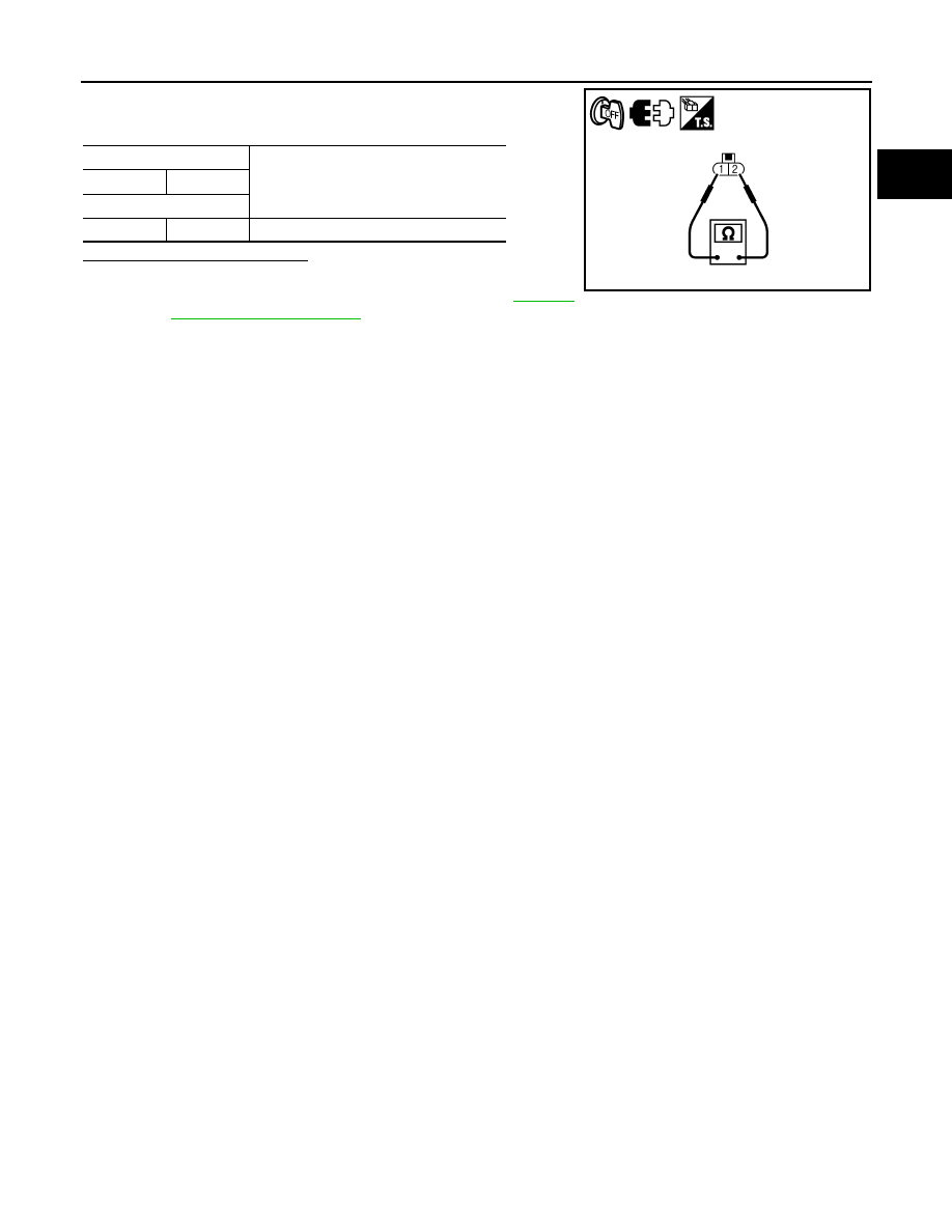
3.
Check resistance between fuel injector terminals as per the fol-
lowing.
Is the inspection result normal?
YES
>> INSPECTION END
NO
>> Replace malfunctioning fuel injector. Refer to
.
Fuel injector
Resistance
+
-
Terminal
1
2
11.1 - 14.5
Ω
[at 10 - 60
°
C (50 - 140
°
F)]
PBIA9579J