содержание .. 898 899 900 901 ..
Nissan X-Trail 32. Manual - part 900
P1572 BRAKE PEDAL POSITION SWITCH
EC-729
< DTC/CIRCUIT DIAGNOSIS >
[QR25DE]
C
D
E
F
G
H
I
J
K
L
M
A
EC
N
P
O
P1572 BRAKE PEDAL POSITION SWITCH
DTC Description
INFOID:0000000010986437
DTC DETECTION LOGIC
NOTE:
This self-diagnosis has the one trip detection logic. When malfunction A is detected, DTC is not stored
in ECM memory. And in that case, 1st trip DTC and 1st trip freeze frame data are displayed. 1st trip
DTC is erased when ignition switch OFF. And even when malfunction A is detected in two consecutive
trips, DTC is not stored in ECM memory.
POSSIBLE CAUSE
• Harness or connectors
- Stop lamp switch circuit is shorted.
- Brake pedal position switch circuit is shorted.
• Stop lamp switch
• Brake pedal position switch
• Incorrect stop lamp switch installation
• Incorrect brake pedal position switch installation
• ECM
FAIL-SAFE
Not applicable
DTC CONFIRMATION PROCEDURE
1.
CHECK DTC PRIORITY
If DTC P1572 is displayed with DTC P0603, P0604, P0605, P606, P0607, P060A, or P060B, first perform the
trouble diagnosis for DTC P0603, P0604, P0605, P606, P0607, P060A, or P060B.
Is applicable DTC detected?
YES
>> Perform diagnosis of applicable. Refer to
NO
>> GO TO 2.
2.
PRECONDITIONING
If DTC Confirmation Procedure has been previously conducted, always perform the following procedure
before conducting the next test.
1.
Turn ignition switch OFF and wait at least 10 seconds.
2.
Turn ignition switch ON.
3.
Turn ignition switch OFF and wait at least 10 seconds.
NOTE:
Procedure for malfunction B is not described here. It takes extremely long time to complete procedure for mal-
function B. By performing procedure for malfunction A, the incident that causes malfunction B can be
detected.
>> GO TO 3.
3.
PERFORM DTC CONFIRMATION PROCEDURE FOR MALFUNCTION A
1.
Start engine.
2.
Press MAIN switch and make sure that CRUISE indicator is displayed in combination meter.
3.
Drive the vehicle for at least 5 consecutive seconds as per the following conditions.
CAUTION:
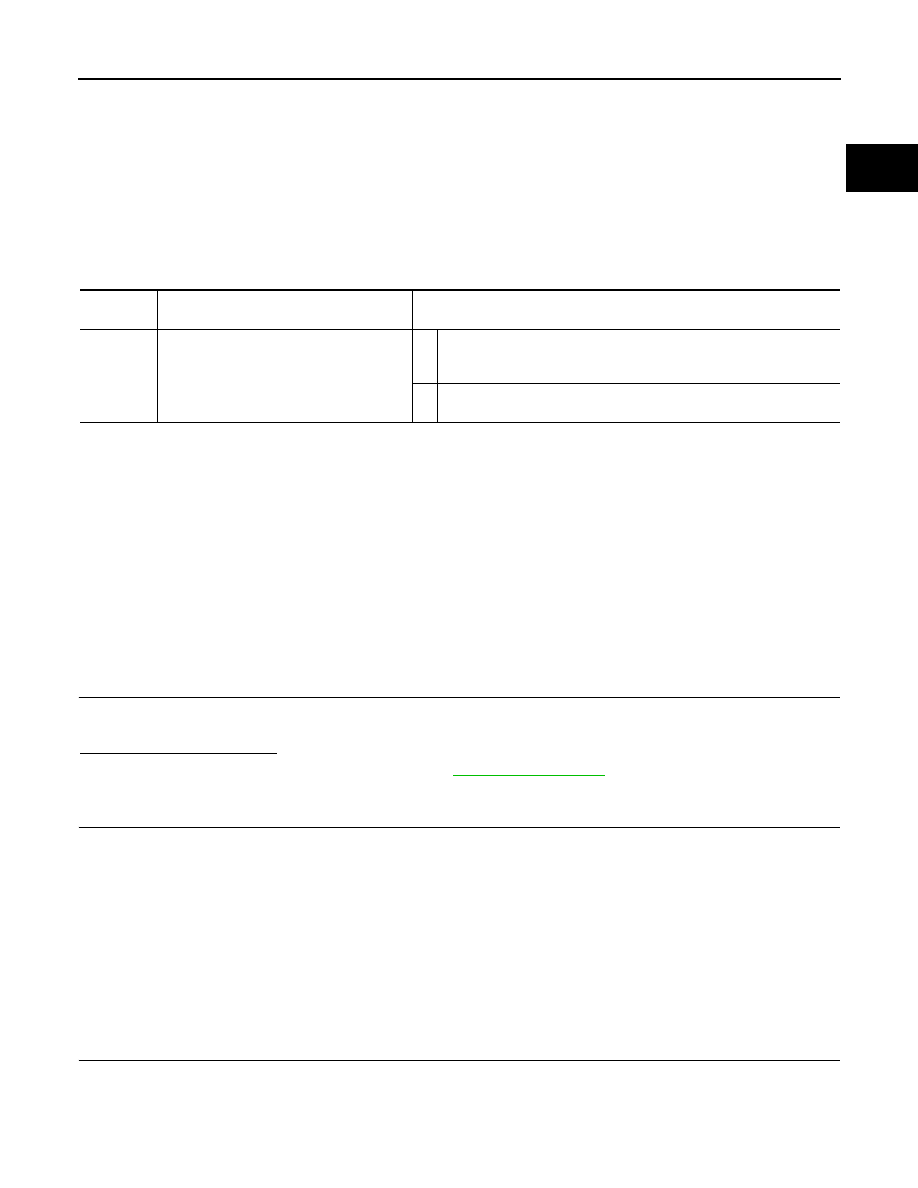
DTC No.
CONSULT screen terms
(Trouble diagnosis content)
DTC detecting condition
P1572
ASCD BRAKE SW
(ASCD BRAKE SW)
A
When the vehicle speed is above 30 km/h (19 MPH), ON signals from
the stop lamp switch and the brake pedal position switch are sent to
the ECM at the same time.
B
Brake pedal position switch signal is not sent to ECM for extremely
long time while the vehicle is driving.