содержание .. 888 889 890 891 ..
Nissan X-Trail 32. Manual - part 890
P0444 EVAP CANISTER PURGE VOLUME CONTROL SOLENOID VALVE
EC-689
< DTC/CIRCUIT DIAGNOSIS >
[QR25DE]
C
D
E
F
G
H
I
J
K
L
M
A
EC
N
P
O
Component Inspection
INFOID:0000000010986376
1.
CHECK EVAP CANISTER PURGE VOLUME CONTROL SOLENOID VALVE
With CONSULT
1.
Turn ignition switch OFF.
2.
Reconnect all harness connectors disconnected.
3.
Disconnect EVAP purge hoses connected to EVAP canister purge volume control solenoid valve.
4.
Start engine.
5.
Select “PURG VOL CONT/V” in “ACTIVE TEST” mode of “ENGINE” using CONSULT.
6.
Touch “Qd” and “Qu” on CONSULT screen to adjust “PURG
VOL C/V” opening and check air passage continuity of EVAP
canister purge volume control solenoid valve as per the follow-
ing conditions.
Without CONSULT
1.
Turn ignition switch OFF.
2.
Disconnect EVAP canister purge volume control solenoid valve harness connector.
3.
Disconnect EVAP purge hoses connected to EVAP canister purge volume control solenoid valve.
4.
Check air passage continuity of EVAP canister purge volume
control solenoid valve as per the following conditions.
Is the inspection result normal?
YES
>> INSPECTION END
NO
>> Replace EVAP canister purge volume control solenoid valve. Refer to
.
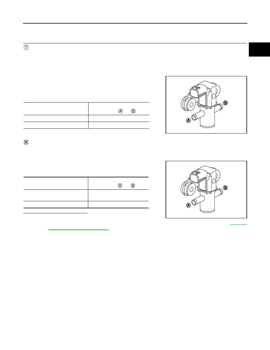
Condition
(PURG VOL C/V value)
Air passage continuity
between
and
100%
Existed
0%
Not existed
JMBIA0068ZZ
Condition
Air passage continuity
between
and
12 V direct current supply between
terminals 1 and 2
Existed
No supply
Not existed
JMBIA0068ZZ