Nissan X-Trail 32. Manual - part 840


  Главная      Nissan     Nissan X-Trail 32 - Service Manual


поиск по сайту            


содержание   ..  838  839  840  841   ..


Nissan X-Trail 32. Manual - part 840


DIAGNOSIS SYSTEM (ECM)

EC-489

< SYSTEM DESCRIPTION >

[QR25DE]

C

D

E

F

G

H

I

J

K

L

M

A

EC

N

P

O

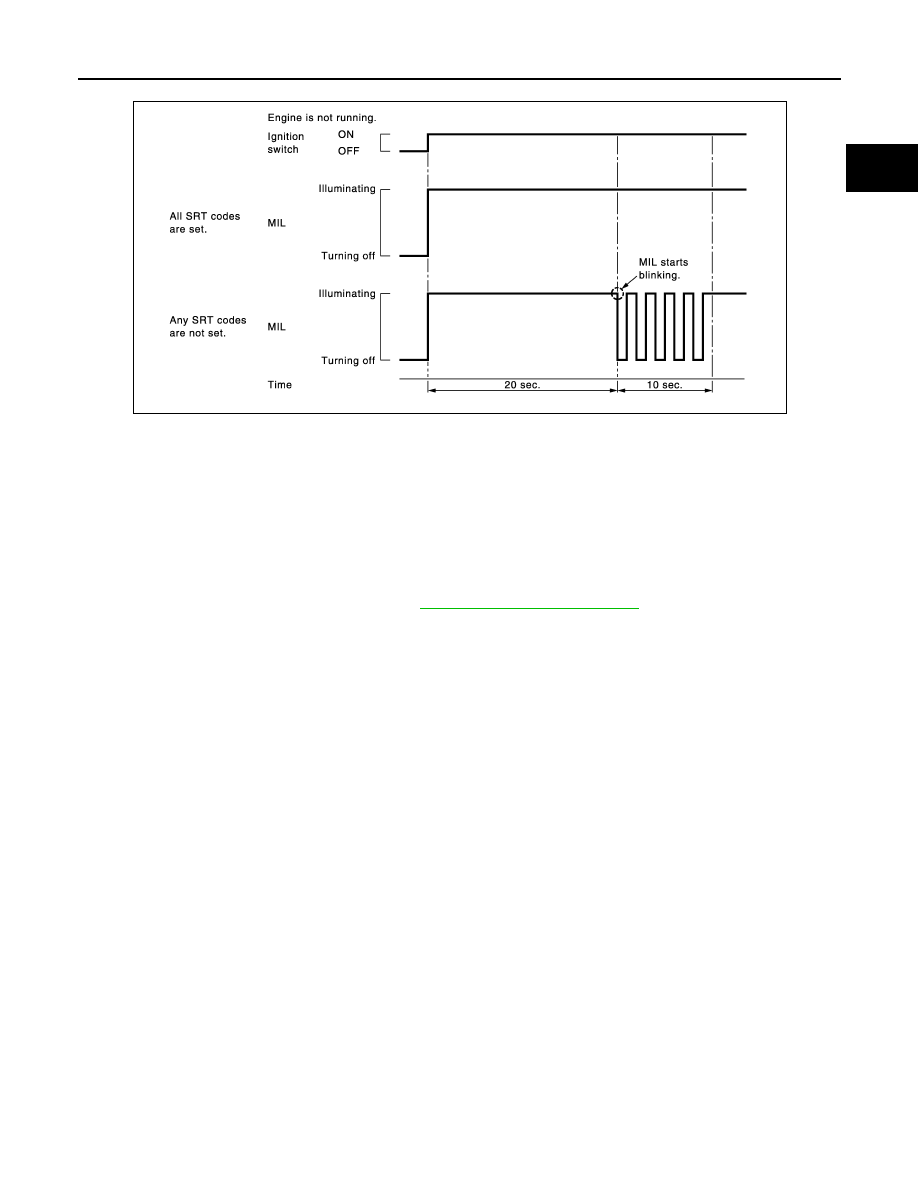
• ECM blinks MIL for about 10 seconds if all SRT codes are not set.

MALFUNCTION WARNING MODE

Description

In this function ECM turns on or blinks MIL when it detects a malfunction in the emission control system com-
ponents and/or the powertrain control components (which affect vehicle emissions) to inform the driver that a
malfunction has been detected.

Operation Procedure

1.

Turn ignition switch ON.

2.

Check that MIL illuminates.
If it remains OFF, check MIL circuit. Refer to 

EC-791, "Diagnosis Procedure"

.

3.

Start engine and let it idle.
• For two trip detection logic diagnoses, ECM turns on MIL when it detects the same malfunction twice in

the two consecutive driving cycles.

• For 1st trip detection logic diagnoses, ECM turns on MIL when it detects a malfunction in one driving

cycle.

• ECM blinks MIL when it detects a malfunction that may damage the three way catalyst (misfire).

SELF-DIAGNOSTIC RESULTS MODE

Description

This function allows to indicate DTCs or 1st trip DTCs stored in ECM according to the number of times MIL is
blinking.

How to Set Self-diagnostic Results Mode

NOTE:
• It is better to count the time accurately with a clock.
• It is impossible to switch the diagnostic mode when an accelerator pedal position sensor circuit has a mal-

function.

• After ignition switch is turned off, ECM is always released from the “self-diagnostic results” mode.
1.

Confirm that accelerator pedal is fully released, turn ignition switch ON and wait 3 seconds.

2.

Repeat the following procedure quickly five times within 5 seconds.
• Fully depress the accelerator pedal.
• Fully release the accelerator pedal.

3.

Wait 7 seconds, fully depress the accelerator pedal and keep it depressed for approx. 10 seconds until the
MIL starts blinking.
NOTE:
Do not release the accelerator pedal for 10 seconds if MIL starts blinking during this period. This blinking
is displaying SRT status and is continued for another 10 seconds.

4.

Fully release the accelerator pedal.
ECM has entered to “Self-diagnostic results” mode.

JMBIA1515GB

EC-490

< SYSTEM DESCRIPTION >

[QR25DE]

DIAGNOSIS SYSTEM (ECM)

NOTE:
Wait until the same DTC (or 1st trip DTC) appears to completely confirm all DTCs.

How to Read Self-diagnostic Results

The DTC and 1st trip DTC are indicated by the number of blinks of the MIL as shown below.
The DTC and 1st trip DTC are displayed at the same time. If the MIL does not illuminate in diagnostic test
mode I (Malfunction warning), all displayed items are 1st trip DTCs. If only one code is displayed when the MIL
illuminates in “malfunction warning” mode, it is a DTC; if two or more codes are displayed, they may be either
DTCs or 1st trip DTCs. DTC No. is same as that of 1st trip DTC. These unidentified codes can be identified by
using the CONSULT or GST. A DTC will be used as an example for how to read a code.

A particular trouble code can be identified by the number of four-digit numeral flashes per the following.

The length of time the 1,000th-digit numeral flashes on and off is 1.2 seconds consisting of an ON (0.6-sec-
onds) - OFF (0.6-seconds) cycle.
The 100th-digit numeral and lower digit numerals consist of a 0.3-seconds ON and 0.3-seconds OFF cycle.
A change from one digit numeral to another occurs at an interval of 1.0-second OFF. In other words, the later
numeral appears on the display 1.3 seconds after the former numeral has disappeared.
A change from one trouble code to another occurs at an interval of 1.8-seconds OFF.

PBIB0092E

PBIB3005E

Number

0

1

2

3

4

5

6

7

8

9

A

B

C

D

E

F

Flashes

10

1

2

3

4

5

6

7

8

9

11

12

13

14

15

16

DIAGNOSIS SYSTEM (ECM)

EC-491

< SYSTEM DESCRIPTION >

[QR25DE]

C

D

E

F

G

H

I

J

K

L

M

A

EC

N

P

O

In this way, all the detected malfunctions are classified by their DTC numbers. The DTC 0000 refers to no mal-
function. Refer to 

EC-517, "DTC Index"

.

How to Erase Self-diagnostic Results

By performing this procedure, ECM memory is erased and the following diagnostic information is erased as
well.
• Diagnostic trouble codes
• 1st trip diagnostic trouble codes
• Freeze frame data
• 1st trip freeze frame data
• System readiness test (SRT) codes
• Test values
NOTE:
Also, if a battery terminal is disconnected, ECM memory is erased and the diagnostic information as listed
above is erased. (The amount of time required for erasing may vary from a few seconds to several hours.)

1.

Turn ignition switch OFF and wait at least 10 seconds.

2.

Turn ignition switch ON.

3.

Turn ignition switch OFF and wait at least 10 seconds.

4.

Turn ignition switch ON.

5.

Set ECM in “self-diagnostic results” mode.

6.

The diagnostic information has been erased from the backup memory in the ECM.
Fully depress the accelerator pedal and keep it depressed for more than 10 seconds.

7.

Fully release the accelerator pedal, and confirm the DTC 0000 is displayed.

CONSULT Function

INFOID:0000000010986260

FUNCTION

*: The following emission-related diagnostic information is cleared when the ECM memory is erased.

• Diagnostic trouble codes

• 1st trip diagnostic trouble codes

• Freeze frame data

• 1st trip freeze frame data

• System readiness test (SRT) codes

• Test  values

SELF DIAGNOSTIC RESULT MODE

Self Diagnostic Item

Regarding items of DTC and 1st trip DTC, refer to 

EC-517, "DTC Index"

.)

How to Read DTC and 1st Trip DTC

DTCs and 1st trip DTCs related to the malfunction are displayed in “self-diag results”.
• When ECM detects a 1st trip DTC, 1t” is displayed for “TIME”.
• When ECM has detected a current DTC, “0” is displayed for “TIME”.
• If “TIME” is neither “0” nor “1t”, the DTC occurred in the past and ECM shows the number of times the vehi-

cle has been driven since the last detection of the DTC.

Diagnostic test mode

Function

Self Diagnostic Result

Self-diagnostic results such as 1st trip DTC, DTC and 1st trip freeze frame data or freeze frame data 
can be read and erased quickly.*

Data Monitor

Input/Output data in the ECM can be read.

Work support

This mode enables a technician to adjust some devices faster and more accurately by following the in-
dications on the CONSULT screen.

Active Test

Diagnostic Test Mode in which CONSULT drives some actuators apart from the ECMs and also shifts 
some parameters in a specified range.

ECU Identification

ECM part number can be read.

DTC Work Support

The status of system monitoring tests and the self-diagnosis status/results can be confirmed.

EC-492

< SYSTEM DESCRIPTION >

[QR25DE]

DIAGNOSIS SYSTEM (ECM)

How to Erase DTC and 1st Trip DTC

NOTE:
If the ignition switch stays ON after repair work, be sure to turn ignition switch OFF once. Wait at least 10 sec-
onds and then turn it ON (engine stopped) again.

Freeze Frame Data and 1st Trip Freeze Frame Data

*: The items are the same as those of 1st trip freeze frame data.

DATA MONITOR MODE

NOTE:
The following table includes information (items) inapplicable to this vehicle. For information (items) applicable
to this vehicle, refer to CONSULT display items.

Monitored Item

Freeze frame data item*

Description

DIAG TROUBLE CODE
[PXXXX]

• The engine control component part/control system has a trouble code that is displayed as PXXXX. (Re-

fer to 

EC-517, "DTC Index"

.)

FUEL SYS-B1

• “Fuel injection system status” at the moment a malfunction is detected is displayed.
- One of the following mode is displayed.
- Mode2: Open loop due to detected system malfunction
- Mode3: Open loop due to driving conditions (power enrichment, deceleration enleanment)
- Mode4: Closed loop - using oxygen sensor(s) as feedback for fuel control
- Mode5: Open loop - has not yet satisfied condition to go to closed loop

CAL/LD VALUE [%]

• The calculated load value at the moment a malfunction is detected is displayed.

COOLANT TEMP
[

°

C] or [

°

F]

• The engine coolant temperature at the moment a malfunction is detected is displayed.

L-FUEL TRM-B1 [%]

• “Long-term fuel trim” at the moment a malfunction is detected is displayed.
• The long-term fuel trim indicates much more gradual feedback compensation to the base fuel schedule 

than short-term fuel trim.

S-FUEL TRM-B1 [%]

• “Short-term fuel trim” at the moment a malfunction is detected is displayed.
• The short-term fuel trim indicates dynamic or instantaneous feedback compensation to the base fuel 

schedule.

ENGINE SPEED [rpm]

• The engine speed at the moment a malfunction is detected is displayed.

VEHICL SPEED
[km/h] or [mph]

• The vehicle speed at the moment a malfunction is detected is displayed.

ABSOL TH·P/S [%]

• The throttle valve opening angle at the moment a malfunction is detected is displayed.

B/FUEL SCHDL [msec]

• The base fuel schedule at the moment a malfunction is detected is displayed.

INT/A TEMP SE
[

°

C] or [

°

F]

• The intake air temperature at the moment a malfunction is detected is displayed.

FUEL SYS-B2

• There items are displayed but are not applicable to this model.

L-FUEL TRM-B2 [%]

S-FUEL TRM-B2 [%]

INT MANI PRES [kPa] 

COMBUST CONDITION


содержание   ..  838  839  840  841   ..