содержание .. 810 811 812 813 ..
Nissan X-Trail 32. Manual - part 812
P2127, P2128 APP SENSOR
EC-377
< DTC/CIRCUIT DIAGNOSIS >
[MR20DD]
C
D
E
F
G
H
I
J
K
L
M
A
EC
N
P
O
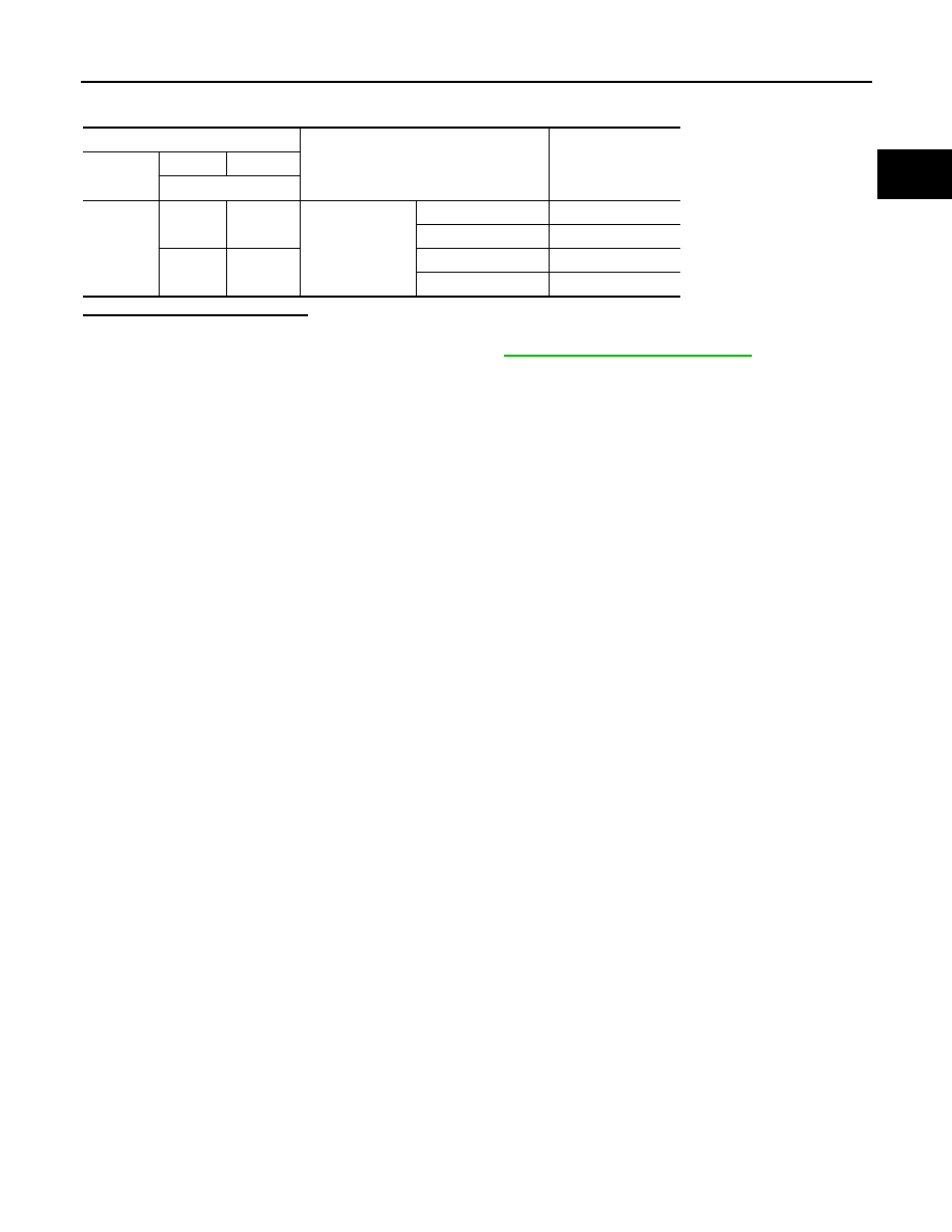
4.
Check the voltage between ECM harness connector terminals as per the following condition.
Is the inspection result normal?
YES
>> INSPECTION END
NO
>> Replace accelerator pedal assembly. Refer to
ACC-4, "Removal and Installation"
ECM
Condition
Voltage
(Approx.)
Connector
+
–
Terminal
E16
126
127
Accelerator pedal
Fully released
0.6 - 0.9 V
Fully depressed
3.9 - 4.7 V
119
120
Fully released
0.3 - 0.6 V
Fully depressed
1.95 - 2.4 V