содержание .. 807 808 809 810 ..
Nissan X-Trail 32. Manual - part 809
P2101 ELECTRIC THROTTLE CONTROL FUNCTION
EC-365
< DTC/CIRCUIT DIAGNOSIS >
[MR20DD]
C
D
E
F
G
H
I
J
K
L
M
A
EC
N
P
O
If DTC P2101 is displayed with DTC P2100 or P2119, first perform the trouble diagnosis for DTC P2100 or
P2119.
Is applicable DTC detected?
YES
>> Perform diagnosis of applicable. Refer to
.
NO
>> GO TO 2.
2.
CHECK THROTTLE CONTROL MOTOR RELAY INPUT SIGNAL
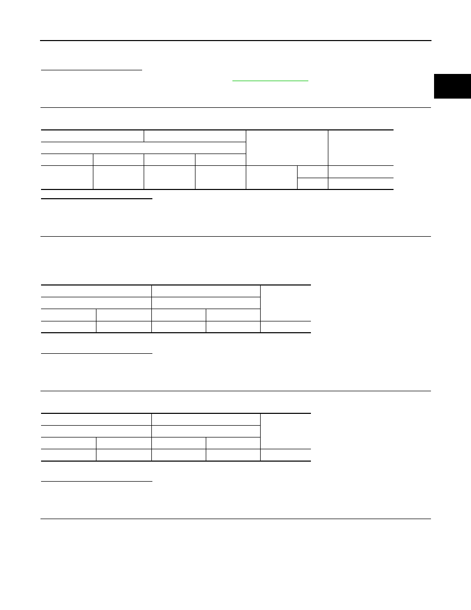
Check the voltage between ECM harness connector terminals as per the following conditions.
Is the inspection result normal?
YES
>> GO TO 5.
NO
>> GO TO 3.
3.
CHECK THROTTLE CONTROL MOTOR RELAY INPUT SIGNAL CIRCUIT
1.
Turn ignition switch OFF.
2.
Disconnect ECM harness connector.
3.
Disconnect IPDM E/R harness connector.
4.
Check the continuity between ECM harness connector and IPDM E/R harness connector.
5.
Also check harness for short to ground and to power.
Is the inspection result normal?
YES
>> GO TO 4.
NO
>> Repair or replace malfunctioning part.
4.
CHECK THROTTLE CONTROL MOTOR RELAY POWER SUPPLY CIRCUIT
1.
Check the continuity between ECM harness connector and IPDM E/R harness connector.
2.
Also check harness for short to ground and to power.
Is the inspection result normal?
YES
>> Perform the trouble diagnosis for power supply circuit.
NO
>> Repair or replace malfunctioning part.
5.
CHECK THROTTLE CONTROL MOTOR OUTPUT SIGNAL CIRCUIT
1.
Turn ignition switch OFF.
2.
Disconnect electric throttle control actuator harness connector.
3.
Disconnect ECM harness connector.
4.
Check the continuity between electric throttle control actuator harness connector and ECM harness con-
nector.
+
−
Condition
Voltage
(Approx.)
ECM
Connector
Terminal
Connector
Terminal
F8
80
E16
128
Ignition switch
OFF
0 V
ON
Battery voltage
+
−
Continuity
ECM
IPDM E/R
Connector
Terminal
Connector
Terminal
F8
80
F72
67
Existed
+
−
Continuity
ECM
IPDM E/R
Connector
Terminal
Connector
Terminal
F8
65
F72
72
Existed