Nissan X-Trail 32. Manual - part 785


  Главная      Nissan     Nissan X-Trail 32 - Service Manual


поиск по сайту            


содержание   ..  783  784  785  786   ..


Nissan X-Trail 32. Manual - part 785


P0300, P0301, P0302, P0303, P0304 MISFIRE

EC-269

< DTC/CIRCUIT DIAGNOSIS >

[MR20DD]

C

D

E

F

G

H

I

J

K

L

M

A

EC

N

P

O

P0301, P0302, P0303, P0304 

Not applicable

DTC CONFIRMATION PROCEDURE

1.

PRECONDITIONING

If DTC Confirmation Procedure has been previously conducted, always turn ignition switch OFF and wait at
least 10 seconds before conducting the next test.

Will CONSULT be used?

YES

>> GO TO 2.

NO

>> GO TO 4.

2.

PERFORM DTC CONFIRMATION PROCEDURE-1

WITH CONSULT

1.

Start engine and warm it up to normal operating temperature.

2.

Turn ignition switch OFF and wait at least 10 seconds.

3.

Restart engine and let it idle for about 35 minutes.

4.

Check 1st trip DTC.

Is 1st trip DTC detected?

YES

>> Proceed to 

EC-270, "Diagnosis Procedure"

.

NO

>> GO TO 3.

3.

PERFORM DTC CONFIRMATION PROCEDURE-2

1.

Turn ignition switch OFF and wait at least 10 seconds.

2.

Start engine and drive the vehicle under similar conditions to (1st trip) Freeze Frame Data for a certain
time. Refer to the table below.
Hold the accelerator pedal as steady as possible.
Similar conditions to (1st trip) Freeze Frame Data mean that the following conditions should be satisfied at
the same time.

Driving time varies according to the engine speed in the freeze frame data.

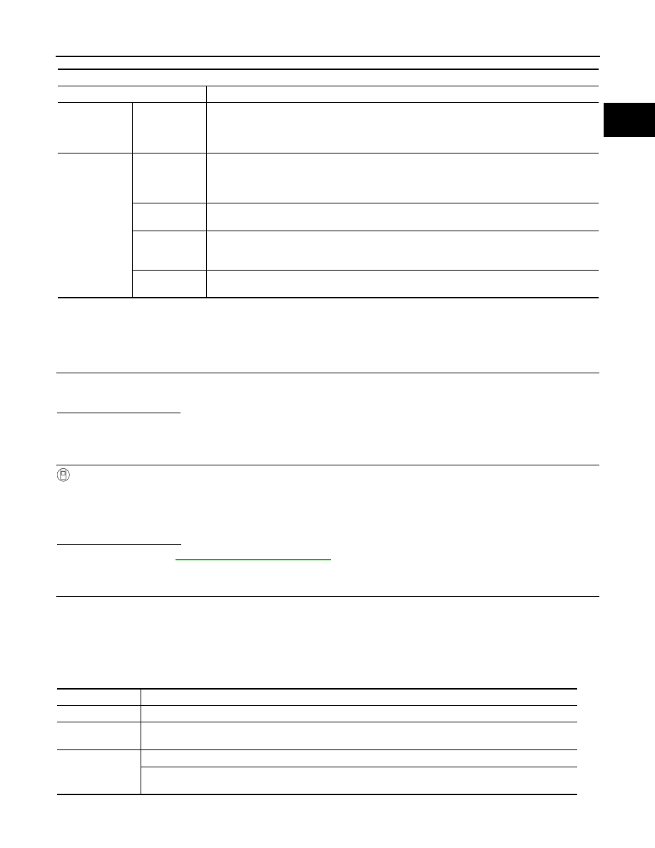
Engine operating condition in fail-safe mode

Fail safe mode

Vehicle behavior

Traveling con-
trol mode

Accelerator an-
gle variation 
control

ECM controls the accelerator pedal depression speed to make it slower than actual speed. This 
causes a drop in accelerating performance and encourages the driver to repair malfunction.
NOTE:
ECM does not control the accelerator pedal releasing speed.

Combustion 
control mode

Stratified charge 
combustion 
control at start-
ing

No stratified charge combustion at starting (cold start).

Idle speed con-
trol

Stops feedback control of idle speed and controls with specified speed.

Recovery speed 
control at decel-
erating

Stops recovery speed control by the fuel cut at decelerating and controls with specified speed.

Idle neutral con-
trol

Stops idle neutral control.

Engine speed

Engine speed in the freeze frame data 

±

 400 rpm

Vehicle speed

Vehicle speed in the freeze frame data 

±

 10 km/h (6 MPH)

Base fuel sched-
ule

Base fuel schedule in the freeze frame data 

±

 10%

Engine coolant 
temperature (T) 
condition

When the freeze frame data shows lower than 70

°

C (158

°

F), T should be lower than 70

°

C (158

°

F).

When the freeze frame data shows higher than or equal to 70

°

C (158

°

F), T should be higher than or equal 

to 70

°

C (158

°

F).

EC-270

< DTC/CIRCUIT DIAGNOSIS >

[MR20DD]

P0300, P0301, P0302, P0303, P0304 MISFIRE

3.

Check 1st trip DTC.

Is 1st trip DTC detected?

YES

>> Proceed to 

EC-270, "Diagnosis Procedure"

.

NO-1

>> To check malfunction symptom before repair: Refer to 

GI-44, "Intermittent Incident"

.

NO-2

>> Confirmation after repair: INSPECTION END

4.

PERFORM DTC CONFIRMATION PROCEDURE-3

WITHOUT CONSULT

1.

Start engine and warm it up to normal operating temperature.

2.

Turn ignition switch OFF and wait at least 10 seconds.

3.

Restart engine and let it idle for about 35 minutes.

4.

Check 1st trip DTC.

Is 1st trip DTC detected?

YES

>> Proceed to 

EC-270, "Diagnosis Procedure"

.

NO-1

>> To check malfunction symptom before repair: Refer to 

GI-44, "Intermittent Incident"

.

NO-2

>> Confirmation after repair: INSPECTION END

Diagnosis Procedure

INFOID:0000000010775173

1.

CHECK FOR INTAKE AIR LEAKAGE AND PCV HOSE

1.

Start engine and run it at idle speed.

2.

Listen for the sound of the intake air leakage.

3.

Check PCV hose connection.

Is intake air leakage detected?

YES

>> Discover air leakage location and repair. Refer to 

EM-54, "Exploded View"

.

NO

>> GO TO 2.

2.

CHECK FOR EXHAUST SYSTEM CLOGGING

Stop engine and visually check exhaust tube, three way catalyst and muffler for dents.

Is the inspection result normal?

YES-1 >> With CONSULT: GO TO 3.
YES-2 >> Without CONSULT: GO TO 4.
NO

>> Repair or replace malfunctioning part. Refer to 

EX-6, "Exploded View"

.

3.

PERFORM POWER BALANCE TEST

WITH CONSULT

1.

Start engine.

2.

Perform “POWER BALANCE” “ACTIVE TEST” mode with CONSULT.

3.

Check that each circuit produces a momentary engine speed drop.

Is the inspection result normal?

YES

>> GO TO 9.

NO

>> GO TO 4.

4.

CHECK FUNCTION OF FUEL INJECTOR

WITHOUT CONSULT

1.

Start engine.

Engine speed

Time

Around 1,000 rpm

Approximately 20 minutes

Around 2,000 rpm

Approximately 10 minutes

More than 3,000 rpm

Approximately 7 minutes

P0300, P0301, P0302, P0303, P0304 MISFIRE

EC-271

< DTC/CIRCUIT DIAGNOSIS >

[MR20DD]

C

D

E

F

G

H

I

J

K

L

M

A

EC

N

P

O

2.

Listen to each fuel injector operation.

Is the inspection result normal?

YES

>> GO TO 5.

NO

>>  Perform trouble diagnosis for fuel injector, refer to 

EC-

386, "Diagnosis Procedure"

.

5.

CHECK FUNCTION OF IGNITION COIL-1

CAUTION:

Perform the following procedure in a place with no combustible objects and good ventilation.
1.

Turn ignition switch OFF.

2.

Remove fuel pump fuse in IPDM E/R to release fuel pressure.
NOTE:
Do not use CONSULT to release fuel pressure, or fuel pressure applies again during the following proce-
dure.

3.

Start engine.

4.

After engine stalls, crank it 2 or 3 times to release all fuel pressure.

5.

Turn ignition switch OFF.

6.

Remove all ignition coil harness connectors to avoid the electrical discharge from the ignition coils.

7.

Remove ignition coil and spark plug of the cylinder to be checked. Refer to 

EM-54, "Exploded View"

.

8.

Crank engine for 5 seconds or more to remove combustion gas in the cylinder.

9.

Connect spark plug and harness connector to ignition coil.

10. Fix ignition coil using a rope etc. with gap of 13 - 17 mm (0.52 -

0.66 in) between the edge of the spark plug and grounded metal
portion as shown in the figure.

11. Crank engine for approximately 3 seconds, and check whether

spark is generated between the spark plug and the grounded
metal portion.

CAUTION:

• Never place the spark plug and the ignition coil within 50

cm (19.7 in) each other. Be careful not to get an electrical
shock while checking, because the electrical discharge voltage becomes 20 kV or more.

• It might damage the ignition coil if the gap of more than 17 mm (0.66 in) is made.
NOTE:
When the gap is less than 13 mm (0.52 in), a spark might be generated even if the coil is malfunctioning.

Is the inspection result normal?

YES

>> GO TO 9.

NO

>> GO TO 6.

6.

CHECK FUNCTION OF IGNITION COIL-2

1.

Turn ignition switch OFF.

2.

Disconnect spark plug and connect a non-malfunctioning spark plug.

3.

Crank engine for approximately 3 seconds, and recheck whether spark is generated between the spark
plug and the grounded metal portion.

Is the inspection result normal?

YES

>> GO TO 7.

NO

>> Check ignition coil, power transistor and their circuits. Refer to 

EC-399, "Diagnosis Procedure"

.

Clicking sound should 
be heard.

PBIB3332E

Spark should be gener-
ated.

JMBIA0066GB

Spark should be gener-
ated.

EC-272

< DTC/CIRCUIT DIAGNOSIS >

[MR20DD]

P0300, P0301, P0302, P0303, P0304 MISFIRE

7.

CHECK SPARK PLUG

Check the initial spark plug for fouling, etc.
Is the inspection result normal?

YES

>> Replace spark plug(s) with standard type one(s). Refer

to 

EM-54, "Exploded View"

.

NO

>> Repair or clean spark plug. Then GO TO 8.

8.

CHECK FUNCTION OF IGNITION COIL-3

1.

Reconnect the initial spark plugs.

2.

Crank engine for approximately 3 seconds, and recheck whether spark is generated between the spark
plug and the grounded portion.

Is the inspection result normal?

YES

>> INSPECTION END

NO

>> Replace spark plug(s) with standard type one(s). Refer to 

EM-54, "Exploded View"

.

9.

CHECK COMPRESSION PRESSURE

Check compression pressure. Refer to 

EM-19, "Inspection"

.

Is the inspection result normal?

YES

>> GO TO 10.

NO

>> Check pistons, piston rings, valves, valve seats and cylinder head gaskets.

10.

CHECK FUEL PRESSURE

1.

Install all removed parts.

2.

Release fuel pressure. Refer to 

EC-152, "Work Procedure"

.

3.

Set a fuel pressure meter and check fuel pressure. Refer to 

EC-152, "Work Procedure"

.

Is the inspection result normal?

YES

>> GO TO 12.

NO

>> GO TO 11.

11.

DETECT MALFUNCTIONING PART

Check fuel hoses and fuel tubes for clogging.
Is the inspection result normal?

YES

>> Replace “fuel filter and fuel pump assembly”. Refer to 

FL-12, "Removal and Installation"

.

NO

>> Repair or replace malfunctioning part.

12.

CHECK IDLE SPEED AND IGNITION TIMING

Check idle speed and ignition timing.
Idle speed: For procedure, refer to 

EC-426, "Inspection"

, for specification, refer to 

EC-431, "Idle Speed"

.

Ignition timing: For procedure, refer to 

EC-427, "Inspection"

, for specification, refer to 

EC-431, "Ignition Tim-

ing"

.

Is the inspection result normal?

YES

>> GO TO 13.

NO

>> Perform basic inspection. Refer to 

EC-149, "Work Procedure"

.

13.

CHECK A/F SENSOR 1 INPUT SIGNAL CIRCUIT

1.

Turn ignition switch OFF.

SEF156I

Spark should be generated.

At idle: Approx. 500 kPa (5.0 bar, 5.1 kg/cm

2

, 73 psi)


содержание   ..  783  784  785  786   ..