Nissan X-Trail 32. Manual - part 728


  Главная      Nissan     Nissan X-Trail 32 - Service Manual


поиск по сайту            


содержание   ..  726  727  728  729   ..


Nissan X-Trail 32. Manual - part 728


COMPONENT PARTS

EC-41

< SYSTEM DESCRIPTION >

[MR20DD]

C

D

E

F

G

H

I

J

K

L

M

A

EC

N

P

O

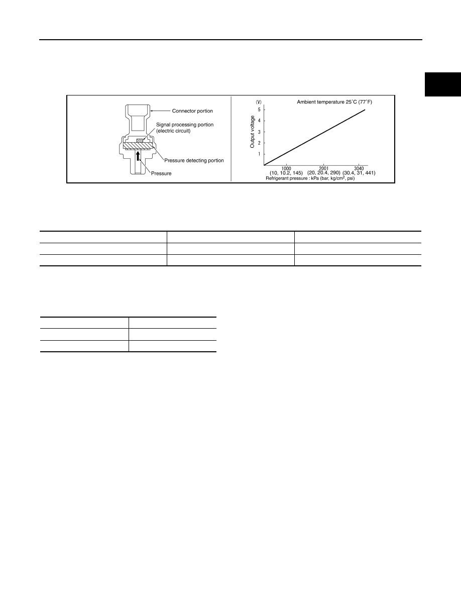
Refrigerant Pressure Sensor

INFOID:0000000010775028

The refrigerant pressure sensor is installed at the liquid tank of the air conditioner system. The sensor uses an
electrostatic volume pressure transducer to convert refrigerant pressure to voltage. The voltage signal is sent
to ECM, and ECM controls cooling fan system.

Stop Lamp Switch and Brake pedal position switch

INFOID:0000000010775029

Stop lamp switch and brake pedal position switch are installed to brake pedal bracket.
ECM detects the state of the brake pedal by those two types of input (ON/OFF signal).

Clutch Pedal Position Switch

INFOID:0000000010775030

Clutch pedal position switch are installed to clutch pedal bracket.
ECM detects the state of the clutch pedal by those two types of input signal (ON/OFF).

ASCD Steering Switch

INFOID:0000000010775031

ASCD steering switch has variant values of electrical resistance for each button. ECM reads voltage variation
of switch, and determines which button is operated.

JSBIA5008GB

Brake pedal

Brake pedal position switch

Stop lamp switch

Released

ON

OFF

Depressed

OFF

ON

Clutch pedal

Clutch pedal position switch

Released

ON

Depressed

OFF

EC-42

< SYSTEM DESCRIPTION >

[MR20DD]

STRUCTURE AND OPERATION

STRUCTURE AND OPERATION

Positive Crankcase Ventilation

INFOID:0000000010775033

This system returns blow-by gas to the intake manifold.The positive
crankcase ventilation (PCV) valve is provided to conduct crankcase
blow-by gas to the intakemanifold.
During partial throttle operation of the engine, the intake manifold
sucks the blow-by gas through the PCV valve.
Normally, the capacity of the valve is sufficient to handle any blow-by
and a small amount of ventilating air.The ventilating air is drawn from
the air inlet tubes into the crankcase. In this process the air passes
throughthe hose connecting air inlet tubes to rocker cover. Under
full-throttle condition, the manifold vacuum is insufficient to draw the
blow-by flow through the valve.The flow goes through the hose con-
nection in the reverse direction.

PBIB2962E

PBIB1588E

SYSTEM

EC-43

< SYSTEM DESCRIPTION >

[MR20DD]

C

D

E

F

G

H

I

J

K

L

M

A

EC

N

P

O

SYSTEM

ENGINE CONTROL SYSTEM

ENGINE CONTROL SYSTEM : System Description

INFOID:0000000010775034

SYSTEM DIAGRAM

SYSTEM DESCRIPTION

JSBIA5005GB

EC-44

< SYSTEM DESCRIPTION >

[MR20DD]

SYSTEM

• The adopted system enables comprehensive engine control. ECM (engine control module) performs various

controls such as fuel injection control, ignition timing control, idling engine speed control, EVAP purge con-
trol and etc., and this system communicates with control unit such as CVT, ABS, etc. via CAN communica-
tion line.

• The adopted diagnostic system corresponding to OBD (on board diagnostic) system enables various func-

tion check and easily malfunction diagnosis in the engine control system.

ENGINE CONTROL SYSTEM : Fail-safe

INFOID:0000000010775035

NON DTC RELATED ITEM

DTC RELATED ITEM

Description

Function

Reference

Fuel injection control

EC-51, "DIG (DIRECT INJECTION GASOLINE) SYSTEM : 
System Description"

Fuel pressure control

EC-54, "FUEL PRESSURE CONTROL : System Description"

Electric ignition control

EC-55, "ELECTRIC IGNITION SYSTEM : System Descrip-
tion"

Idling control 

EC-56, "IDLE SPEED CONTROL : System Description"

Cooling fan control

EC-57, "COOLING FAN CONTROL : System Description"

Intake valve timing control

EC-58, "INTAKE VALVE TIMING CONTROL : System De-
scription"

Exhaust valve timing control

EC-59, "EXHAUST VALVE TIMING CONTROL : System De-
scription"

Intake manifold runner control valve control

EC-61, "INTAKE MANIFOLD RUNNER CONTROL : System 
Description"

Engine protection control (Low engine oil pressure)

EC-62, "ENGINE PROTECTION CONTROL AT LOW EN-
GINE OIL PRESSURE : System Description"

Air conditioning cut control

EC-63, "AIR CONDITIONING CUT CONTROL : System De-
scription"

ASCD (Automatic speed control device)

EC-64, "AUTOMATIC SPEED CONTROL DEVICE (ASCD) : 
System Description"

ECO mode control

EC-65, "ECO MODE SYSTEM : System Description"

Engine/CVT/ABS total control

EC-65, "INTEGRATED CONTROL OF ENGINE, CVT, AND 
ABS : System Description"

EVAP purge control

EC-66, "EVAPORATIVE EMISSION SYSTEM : System De-
scription"

Power generation voltage variable control

EC-66, "POWER GENERATION VOLTAGE VARIABLE CON-
TROL SYSTEM : System Description"

Fail-safe function

EC-103, "Fail-safe"

On board diagnostic (OBD) system

EC-71, "Diagnosis Description"

Detected 

items

Engine operating condition in 

fail-safe mode

Remarks

Malfunction 
indicator lamp 
circuit

Engine speed will not rise more 
than 2,500 rpm due to the fuel 
cut

When there is an open circuit on MIL circuit, the ECM cannot warn the driver by 
lighting up MIL when there is malfunction on engine control system.
Therefore, when electrical controlled throttle and part of ECM related diagnoses are 
continuously detected as NG for 5 trips, ECM warns the driver that engine control 
system malfunctions and MIL circuit is open by means of operating fail safe func-
tion.
The fail safe function also operates when above diagnoses except MIL circuit are 
detected and demands the driver to repair the malfunction.


содержание   ..  726  727  728  729   ..