содержание .. 698 699 700 701 ..
Nissan X-Trail 32. Manual - part 700
STRUCTURE AND OPERATION
DLN-211
< SYSTEM DESCRIPTION >
[REAR PROPELLER SHAFT: C-CVJ-C]
C
E
F
G
H
I
J
K
L
M
A
B
DLN
N
O
P
SYSTEM DESCRIPTION
STRUCTURE AND OPERATION
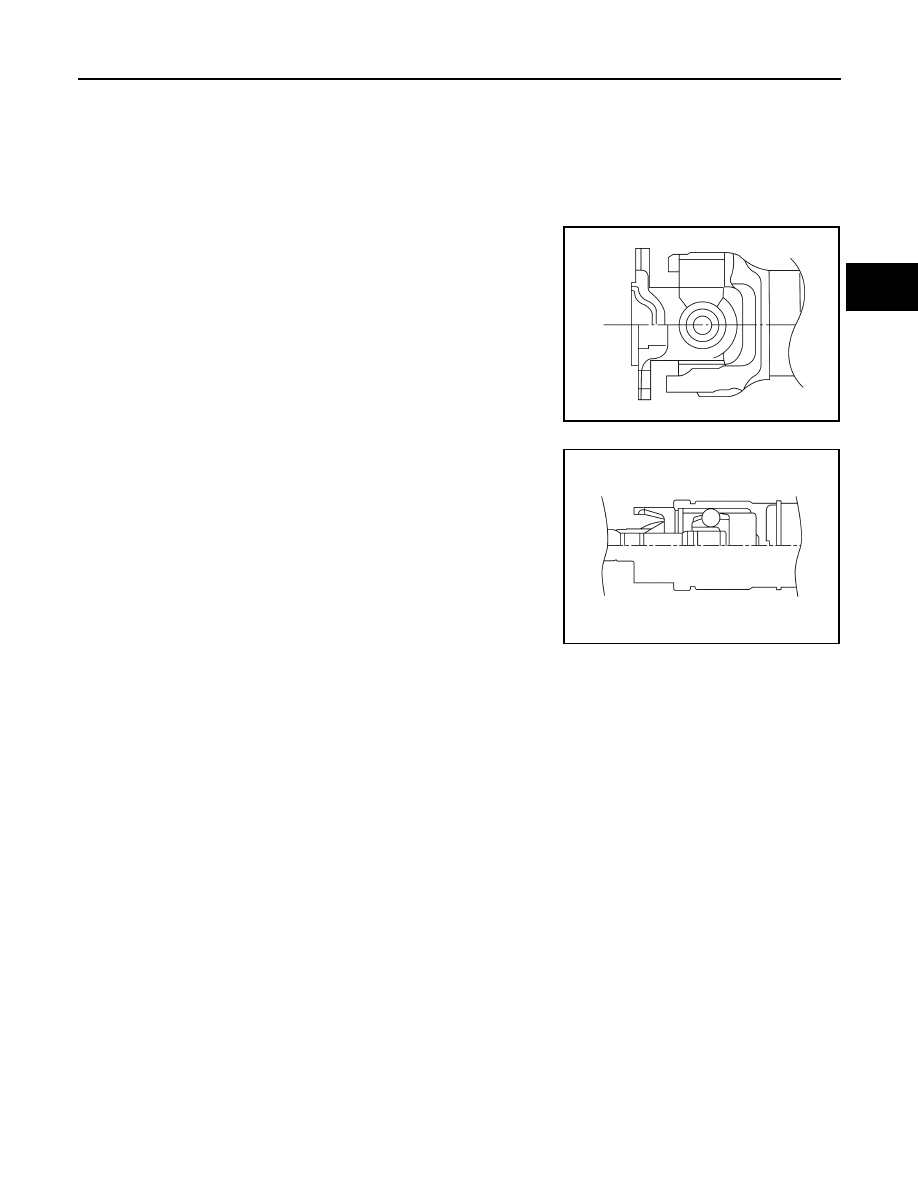
Sectional View
INFOID:0000000010822156
PART OF JOINT
Universal Type (Shell Type)
CVJ Type
JSDIA4709ZZ
JSDIA5322ZZ