содержание .. 669 670 671 672 ..
Nissan X-Trail 32. Manual - part 671
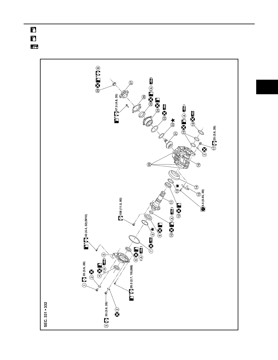
DRIVE PINION
DLN-95
< UNIT DISASSEMBLY AND ASSEMBLY >
[TRANSFER: TY21C]
C
E
F
G
H
I
J
K
L
M
A
B
DLN
N
O
P
QR25DE models
: Apply transfer oil.
*
: Apply anti-corrosive oil.
: Apply multi-purpose grease.
AWDIA1138ZZ