содержание .. 589 590 591 592 ..
Nissan X-Trail 32. Manual - part 591
SUPER LOCK ACTUATOR
DLK-705
< DTC/CIRCUIT DIAGNOSIS >
[TYPE 3]
C
D
E
F
G
H
I
J
L
M
A
B
DLK
N
O
P
Is the inspection result normal?
YES
>> GO TO 3.
NO
>> Repair or replace harness.
3.
CHECK BCM OUTPUT SIGNAL
1.
Connect BCM connector.
2.
Check voltage between BCM harness connector and ground.
Is the inspection result normal?
YES
>> Check for internal short of each door lock actuator.
NO
>> Replace BCM. Refer to
BCS-121, "Removal and Installation"
.
REAR LH
REAR LH : Component Function Check
INFOID:0000000010735370
1.
CHECK FUNCTION
1.
Select “DOOR LOCK” of “BCM” using CONSULT.
2.
Select “SUPER LOCK” in “ACTIVE TEST” mode.
3.
Touch “LOCK” or “UNLOCK” to check that it works normally.
Is the inspection result normal?
YES
>> Super lock actuator is OK.
NO
>> Refer to
DLK-705, "REAR LH : Diagnosis Procedure"
.
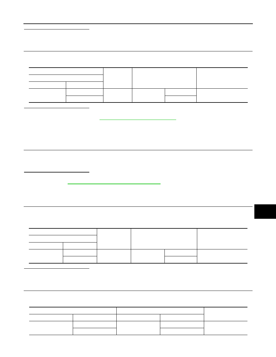
REAR LH : Diagnosis Procedure
INFOID:0000000010735371
1.
CHECK SUPER LOCK ACTUATOR OUTPUT SIGNAL
1.
Turn ignition switch OFF.
2.
Disconnect rear door lock assembly LH.
3.
Check voltage between rear door lock assembly LH harness connector and ground.
Is the inspection result normal?
YES
>> Replace rear door lock assembly LH.
NO
>> GO TO 2.
2.
CHECK SUPER LOCK ACTUATOR CIRCUIT
1.
Disconnect BCM, each door lock actuator and fuel filler lid lock actuator connector.
2.
Check continuity between BCM harness connector and rear door lock assembly LH harness connector.
3.
Check continuity between BCM harness connector and ground.
(+)
(–)
Condition
Voltage
BCM
Connector
Terminal
M85
139
Ground
Super lock
Release
9 – 16 V
149
Set
(+)
(–)
Condition
Voltage
Rear door lock assembly LH
Connector
Terminal
D118
1
Ground
Super lock
Set
9 – 16 V
2
Release
BCM
Rear door lock assembly LH
Continuity
Connector
Terminal
Connector
Terminal
B46
124
D118
2
Existed
131
1