содержание .. 586 587 588 589 ..
Nissan X-Trail 32. Manual - part 588
DOOR LOCK AND UNLOCK SWITCH
DLK-693
< DTC/CIRCUIT DIAGNOSIS >
[TYPE 3]
C
D
E
F
G
H
I
J
L
M
A
B
DLK
N
O
P
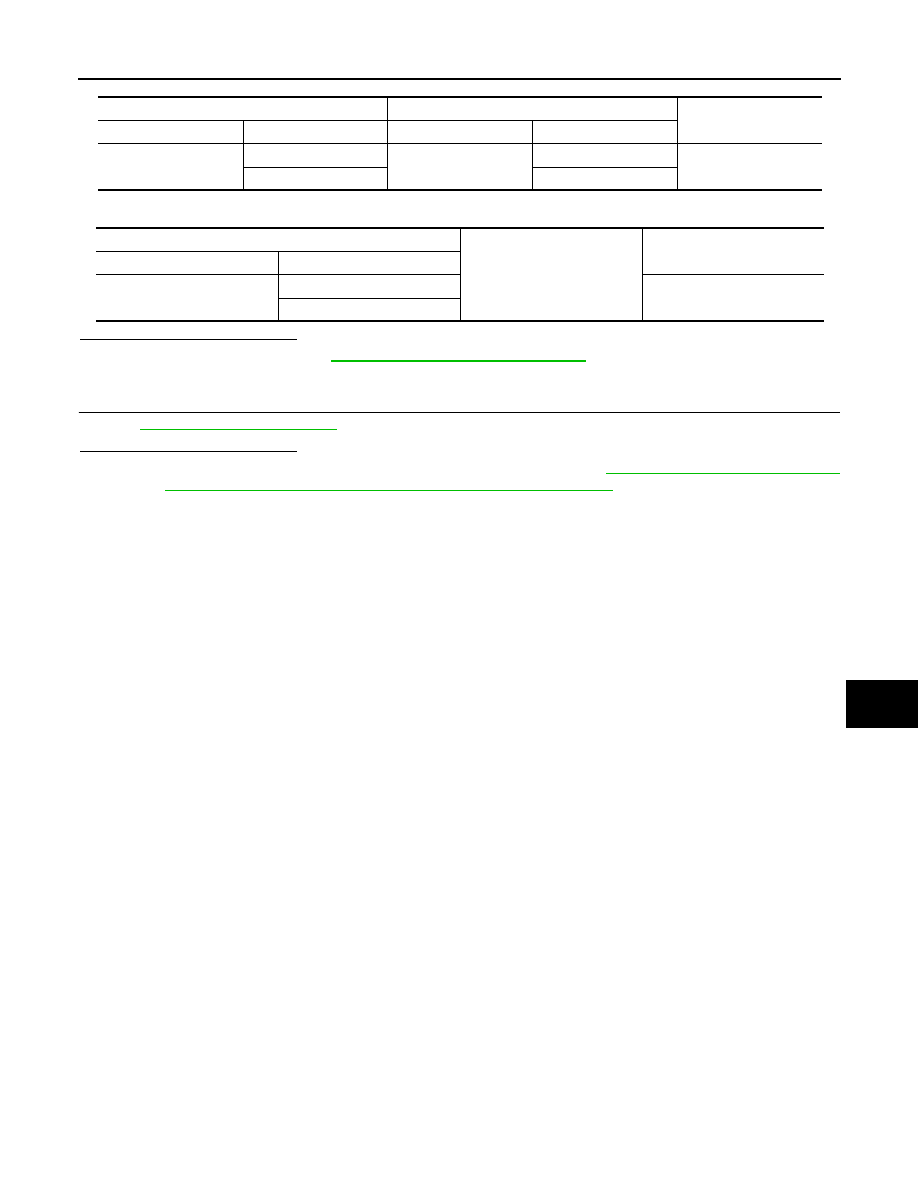
3.
Check continuity between BCM harness connector and ground.
Is the inspection result normal?
YES
>> Replace BCM. Refer to
BCS-121, "Removal and Installation"
.
NO
>> Repair or replace harness.
4.
CHECK INTERMITTENT INCIDENT
GI-44, "Intermittent Incident"
.
Is the inspection result normal?
YES
>> Replace front power window switch (passenger side). Refer to
DOW SWITCH (PASSENGER SIDE) : Removal and Installation"
NO
>> Repair or replace the malfunctioning parts.
BCM
Front power window switch (passenger side)
Continuity
Connector
Terminal
Connector
Terminal
M87
50
D67
1
Existed
80
2
BCM
Ground
Continuity
Connector
Terminal
M87
50
Not existed
80