Nissan X-Trail 32. Manual - part 545


  Главная      Nissan     Nissan X-Trail 32 - Service Manual


поиск по сайту            


содержание   ..  543  544  545  546   ..


Nissan X-Trail 32. Manual - part 545


TOUCH SENSOR

DLK-521

< DTC/CIRCUIT DIAGNOSIS >

[TYPE 2]

C

D

E

F

G

H

I

J

L

M

A

B

DLK

N

O

P

Is the inspection result normal?

YES

>> Touch sensor LH is OK.

NO

>> Refer to 

DLK-521, "LH : Diagnosis Procedure"

.

LH : Diagnosis Procedure

INFOID:0000000010717582

1.

CHECK TOUCH SENSOR INPUT SIGNAL

1.

Turn ignition switch OFF.

2.

Disconnect touch sensor LH connector.

3.

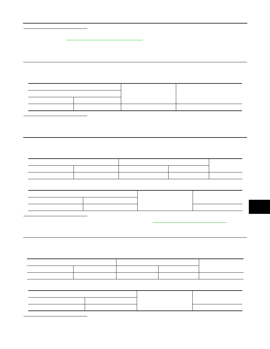
Check voltage between touch sensor LH harness connector and ground.

Is the inspection result normal?

YES

>> GO TO 3.

NO

>> GO TO 2.

2.

CHECK TOUCH SENSOR LH CIRCUIT

1.

Disconnect automatic back door control unit connector.

2.

Check continuity between automatic back door control unit harness connector and touch sensor LH har-
ness connector.

3.

Check continuity between automatic back door control unit harness connector and ground.

Is the inspection result normal?

YES

>> Replace automatic back door control unit. Refer to 

DLK-633, "Removal and Installation"

.

NO

>> Repair or replace harness.

3.

CHECK TOUCH SENSOR LH GROND CIRCUIT

1.

Disconnect automatic back door control unit and touch sensor RH connector.

2.

Check continuity between automatic back door control unit harness connector and touch sensor LH har-
ness connector.

3.

Check continuity between automatic back door control unit harness connector and ground.

Is the inspection result normal?

YES

>> GO TO 4.

NO

>> Repair or replace harness.

(+)

(–)

Voltage

(Approx.)

Touch sensor LH

 Connector

Terminal

D174

1

Ground

6.1 V

Automatic back door control unit

Touch sensor LH 

Continuity 

 Connector

Terminal

 Connector

Terminal

B24

2

D174

1

Existed

Automatic back door control unit

Ground

Continuity 

 Connector

Terminal

B24

2

Not existed

Automatic back door control unit

Touch sensor LH

Continuity 

 Connector

Terminal

Connector

Terminal

B24

13

D174

2

Existed

Automatic back door control unit

Ground

Continuity 

 Connector

Terminal

B24

13

Not existed

DLK-522

< DTC/CIRCUIT DIAGNOSIS >

[TYPE 2]

TOUCH SENSOR

4.

CHECK TOUCH SENSOR LH

Refer to 

DLK-522, "LH : Component Inspection"

.

Is the inspection result normal?

YES

>> GO TO 5.

NO

>> Replace touch sensor LH.

5.

CHECK INTERMITTENT INCIDENT

Refer to 

GI-44, "Intermittent Incident"

.

>> INSPECTION END

LH : Component Inspection

INFOID:0000000010717583

1.

CHECK TOUCH SENSOR LH

1.

Turn ignition switch OFF.

2.

Disconnect touch sensor LH connector.

3.

Check resistance between touch sensor LH terminals.

Is the inspection result normal?

YES

>> INSPECTION END

NO

>> Replace touch sensor LH.

Touch sensor LH

 Condition

Resistance 

(Approx.)

Terminal

1

2

Touch sensor LH

Detect obstruction

380 – 420 k

Other than above

0.95 – 1.05 k

SPINDLE MOTOR

DLK-523

< DTC/CIRCUIT DIAGNOSIS >

[TYPE 2]

C

D

E

F

G

H

I

J

L

M

A

B

DLK

N

O

P

SPINDLE MOTOR

RH

RH : Diagnosis Procedure

INFOID:0000000010717584

1.

CHECK SPINDLE MOTOR INPUT SIGNAL

1.

Turn ignition switch OFF.

2.

Disconnect spindle unit RH connector.

3.

Check voltage between spindle unit RH harness connector and ground.

Is the inspection result normal?

YES

>> Replace spindle unit RH.

NO

>> GO TO 2.

2.

CHECK SPINDLE MOTOR CIRCUIT

1.

Disconnect automatic back door control unit connector.

2.

Check continuity between automatic back door control unit harness connector and spindle unit harness
connector. 

3.

Check continuity between automatic back door control unit harness connector and ground.

Is the inspection result normal?

YES

>> Replace automatic back door control unit. Refer to 

DLK-633, "Removal and Installation"

.

(+)

(–)

Condition

Voltage

(Approx.)

Spindle unit RH

Connector

Terminal

B29

1

Ground

Back door

Auto open op-

eration

12 V

Auto close op-

eration

2

Auto close op-

eration

13.4 V

Auto open op-

eration

JMKIB2776ZZ

JMKIB2776ZZ

Automatic back door control unit

Spindle unit RH

Continuity 

Connector

Terminal

Connector

Terminal

B25

29

B29

1

Existed

36

2

Automatic back door control unit

Ground

Continuity 

Connector

Terminal

B25

29

Not existed

36

DLK-524

< DTC/CIRCUIT DIAGNOSIS >

[TYPE 2]

SPINDLE MOTOR

NO

>> Repair or replace harness.

LH

LH : Diagnosis Procedure

INFOID:0000000010717585

1.

CHECK SPINDLE MOTOR INPUT SIGNAL

1.

Turn ignition switch OFF.

2.

Disconnect spindle unit LH connector.

3.

Check voltage between spindle unit LH harness connector and ground.

Is the inspection result normal?

YES

>> Replace spindle unit LH.

NO

>> GO TO 2.

2.

CHECK SPINDLE MOTOR CIRCUIT

1.

Disconnect automatic back door control unit connector.

2.

Check continuity between automatic back door control unit harness connector and spindle unit LH har-
ness connector. 

3.

Check continuity between automatic back door control unit harness connector and ground.

Is the inspection result normal?

YES

>> Replace automatic back door control unit. Refer to 

DLK-633, "Removal and Installation"

.

(+)

(–)

Condition

Voltage

(Approx.)

Spindle unit LH

Connector

Terminal

B38

1

Ground

Back door

Auto open op-

eration

12 V

Auto close op-

eration

2

Auto close op-

eration

13.4 V

Auto open op-

eration

JMKIB2776ZZ

JMKIB2776ZZ

Automatic back door control unit

Spindle unit LH

Continuity 

Connector

Terminal

Connector

Terminal

B25

27

B38

1

Existed

34

2

Automatic back door control unit

Ground

Continuity 

Connector

Terminal

B25

27

Not existed

34


содержание   ..  543  544  545  546   ..