Nissan X-Trail 32. Manual - part 349


  Главная      Nissan     Nissan X-Trail 32 - Service Manual


поиск по сайту            


содержание   ..  347  348  349  350   ..


Nissan X-Trail 32. Manual - part 349


DAS

REAR WASHER SWITCH INPUT SIGNAL CIRCUIT

DAS-137

< DTC/CIRCUIT DIAGNOSIS >

[DRIVER ASSISTANCE SYSTEM]

C

D

E

F

G

H

I

J

K

L

M

B

N

P

A

REAR WASHER SWITCH INPUT SIGNAL CIRCUIT

Diagnosis Procedure

INFOID:0000000010727946

1.

CHECK COMBINATION SWITCH INPUT SIGNAL CIRCUIT

1.

Turn ignition switch OFF.

2.

Disconnect pump control unit connector and combination switch connector.

3.

Check continuity between combination switch harness connector and pump control unit harness connec-
tor.

4.

Check continuity between pump control unit harness connector and the ground.

Is the inspection result normal?

YES

>> Replace pump control unit. Refer to 

DAS-153, "Removal and Installation"

.

NO

>> Repair harness or connector.
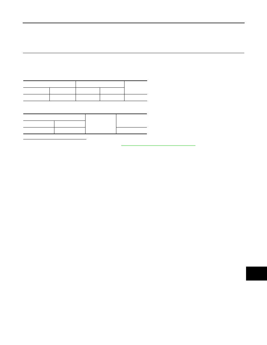
Pump control unit

Combination switch

Continuity

Connector

Terminal

Connector

Terminal

B74

9

M31

11

Existed

Pump control unit

Ground

Continuity

Connector

Terminal

B74

9

Existed

DAS-138

< DTC/CIRCUIT DIAGNOSIS >

[DRIVER ASSISTANCE SYSTEM]

BLIND SPOT WARNING INDICATOR CIRCUIT

BLIND SPOT WARNING INDICATOR CIRCUIT

Diagnosis Procedure

INFOID:0000000010727947

1.

CHECK BSW INDICATOR CIRCUIT FOR OPEN 1

1.

Turn ignition switch OFF.

2.

Disconnect around view monitor control unit harness connector and BSW indicator harness connector.

3.

Check continuity between around view monitor control unit harness connector and BSW indicator harness
connector.

Is the inspection result normal?

YES

>> GO TO 2.

NO

>> Repair the harnesses or connectors.

2.

CHECK BSW INDICATOR CIRCUIT FOR OPEN 2

Check continuity between BSW indicator harness connector and ground.

Is the inspection result normal?

YES

>> GO TO 3.

NO

>> Repair the harnesses or connectors.

3.

CHECK BSW INDICATOR CIRCUIT FOR SHORT

1.

Turn ignition switch OFF.

2.

Check continuity between around view monitor control unit harness connector and ground.

Is the inspection result normal?

YES

>> GO TO 4.

NO

>> Repair the harnesses or connectors.

4.

CHECK AROUND VIEW MONITOR CONTROL UNIT VOLTAGE OUTPUT

1.

Connect around view monitor control unit harness connector.

2.

Check voltage between BSW indicator harness connector and ground.

Around view monitor control 

unit

BSW indicator

Continuity

Connector

Terminal

Connector

Terminal

M101

7

D30  (LH)

1

Existed

8

D12 (RH)

BSW indicator

Ground

Continuity

Connector

Terminal

D30 (LH)

4

Existed

D12 (RH)

Around view monitor control 

unit

Ground

Continuity

Connector

Terminal

M101

7

Not existed

8

DAS

BLIND SPOT WARNING INDICATOR CIRCUIT

DAS-139

< DTC/CIRCUIT DIAGNOSIS >

[DRIVER ASSISTANCE SYSTEM]

C

D

E

F

G

H

I

J

K

L

M

B

N

P

A

Is the inspection result normal?

YES

>> Replace BSW indicator.

NO

>> Replace the around view monitor control unit. Refer to 

AV-268, "Removal and Installation"

.

Terminal

Condition

Voltage

(Approx.)

(+)

(

)

BSW indicator

Ground

Connector

Terminal

D30 (LH)

1

Approx. 2 sec. 
after ignition 
switch
OFF 

 ON

12 V

D12 (RH)

DAS-140

< SYMPTOM DIAGNOSIS >

[DRIVER ASSISTANCE SYSTEM]

DRIVER ASSISTANCE SYSTEM SYMPTOMS

SYMPTOM DIAGNOSIS

DRIVER ASSISTANCE SYSTEM SYMPTOMS

Symptom Table

INFOID:0000000010727948

Before performing diagnosis, check that it is not a symptom caused by normal operation. Refer to 

DAS-147,

"Description"

.

Symptom

Confirmation item

Inspection item/Reference page

LDW/BSW system display does 
not illuminate

All of system display does not illuminate

System settings cannot be 
turned ON/OFF
Refer to 

DAS-142, "Diagnosis 

Procedure"

Other information display is not illuminated

Combination meter
Refer to 

MWI-105, "DTC Index"

LDW/BSW warning display does 
not illuminate (Buzzer is func-
tioning normally)

Information display is func-
tioning normally

LDW

Remove the front camera unit
Refer to 

DAS-149, "Removal 

and Installation"

.

BSW

Remove the around view moni-
tor control unit
Refer to 

AV-268, "Removal and 

Installation"

.

Information display is not functioning normally

On board diagnosis function 
(Combination meter)
Refer to 

MWI-84, "On Board Di-

agnosis Function"

.

LDW/BSW/DAA warning buzzer 
is not sounding (Warning display 
is functioning normally)

Chime does not sound. Refer to 

DAS-143, "Diagnosis Proce-
dure"

.

LDW is not functioning normally

LDW system operates even when using turn signal

LDW system operates even 
when using turn signal
Refer to 

DAS-145, "Diagnosis 

Procedure"

.

Warning functions are not timely
• Does not function when driving on lane markers
• Functions when driving in a lane
• Functions in a different position from the actual position

Front camera unit aiming adjust-
ment
Refer to 

DAS-100, "Work Proce-

dure (Preparation)"

.

BSW is not functioning normally

The system operates once but is cancelled

Check cause of auto-cancel with 
BSW
Refer to 

DAS-45, "CONSULT 

Function"

.

BSW system does not operates even when using turn signal

BSW system does not operates 
even when using turn signal. Re-
fer to 

DAS-146, "Diagnosis Pro-

cedure"

.

BSW indicator does not illuminate

Refer to 

DAS-138, "Diagnosis 

Procedure"

.

Warning functions are not timely
• Does not function when approaching to an adjacent vehicle
• Functions even when the vehicle does not approach to an 

adjacent vehicle.

• Functions in a different position from the actual position
• Functions when driving in the middle of lane

Rear camera calibration
Refer to 

DAS-110, "Work Proce-

dure (Preparation)"

.

Rear camera washer is not acti-
vated (Windshield washer is 
functioning normally)

Refer to 

DAS-135, "Component 

Function Check"

.

Rear camera wash is insufficient

Refer to 

DAS-106, "Inspection 

Procedure"

.


содержание   ..  347  348  349  350   ..