Nissan X-Trail 32. Manual - part 312


  Главная      Nissan     Nissan X-Trail 32 - Service Manual


поиск по сайту            


содержание   ..  310  311  312  313   ..


Nissan X-Trail 32. Manual - part 312


CO-74

< REMOVAL AND INSTALLATION >

[R9M]

RADIATOR

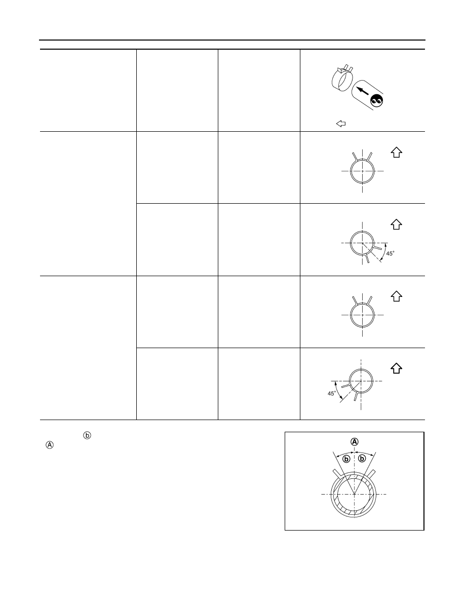
*Refer to the illustrations for the specific position each hose clamp tab.

• The angle 

 created by the hose clamp pawl and the specified line

 must be within 

±

30

°

 as shown in the figure.

Radiator hose

Hose end

Paint mark

Position of hose clamp*

: Vehicle upper

Radiator hose (upper)

Radiator side

Upper

Engine side

Upper 

Radiator hose (lower)

Radiator side

Upper

Engine side

Front

JPCIA0366ZZ

JPCIA0362ZZ

JPBIA6939ZZ

JPCIA0362ZZ

JPBIA6940ZZ

JPBIA4295ZZ

RADIATOR

CO-75

< REMOVAL AND INSTALLATION >

[R9M]

C

D

E

F

G

H

I

J

K

L

M

A

CO

N

P

O

• To install hose clamps 

, check that the dimension (A) from the

hose end to the hose clamp is within the reference value. 

Inspection

INFOID:0000000010782999

INSPECTION AFTER INSTALLATION

• Check for leakage of engine coolant using the radiator cap tester adapter (commercial service tool) and the

radiator cap tester (commercial service tool). Refer to 

CO-64, "Inspection"

.

• Start and warm up the engine. Visually check that there is no leakage of engine coolant.

Dimension “A”

3 - 5 mm

0.12 - 0.20 in

JPBIA3527ZZ

CO-76

< REMOVAL AND INSTALLATION >

[R9M]

COOLING FAN

COOLING FAN

Exploded View

INFOID:0000000010783000

Removal and Installation

INFOID:0000000010783001

REMOVAL

1.

Remove engine under cover. Refer to 

EXT-39, "ENGINE UNDER COVER : Exploded View"

.

2.

Drain engine coolant from radiator. Refer to 

CO-64, "Draining"

.

CAUTION:

• Perform this step when engine is cold.
• Never spill engine coolant on drive belts.

3.

Remove air duct 1 and air duct 2. Refer to 

EM-308, "Exploded View"

.

4.

Remove radiator hose (upper) from radiator. Refer to 

CO-70, "Exploded View"

.

5.

Remove air inlet tube 2 and air inlet hose 2. Refer to 

EM-308, "Exploded View"

.

6.

Remove front grille. Refer to 

EXT-22, "Exploded View"

.

7.

Remove crash zone sensor. Refer to 

SR-31, "Exploded View"

.

8.

Remove hood lock bell crank and hood lock assembly. Refer to folloing table:

How to select vehicle type: refer to 

DLK-22, "Information"

.

9.

Disconnect harness connectors from cooling fan and fan resistor, and move harness to aside.

Cooling fan assembly

Fan resistor

JPBIA6922ZZ

TYPE

Reference

1

DLK-297, "Exploded View"

2

DLK-605, "Exploded View"

3

DLK-768, "Exploded View"

4

DLK-910, "Exploded View"

COOLING FAN

CO-77

< REMOVAL AND INSTALLATION >

[R9M]

C

D

E

F

G

H

I

J

K

L

M

A

CO

N

P

O

10. Remove mounting bolts 

 and clips 

 of mounting bracket 

.

11. Remove radiator core support upper. Refer to folloing table:

How to select vehicle type: refer to 

DLK-22, "Information"

.

12. Remove cooling fan assembly according to the following instructions:

a.

Remove screws 

.

b.

Unlock pawl 

 (

1), and side mounting part 

 (

2).

c.

Remove cooling fan assembly 

 to upward of vehicle (

3).

CAUTION:

Be careful not to damage or scratch on radiator core when
removing.

13. Remove fan resistor, if necessary.

INSTALLATION

Note the following, and install in the reverse order of removal.

CAUTION:

Only use genuine parts for fan shroud mounting bolt and observe the specified torque (to prevent
radiator from being damaged).
NOTE:
Cooling fans are controlled by ECM. For details. Refer to 

EC-843, "COOLING FAN CONTROL : System

Description"

.

Inspection

INFOID:0000000010783003

INSPECTION AFTER DISASSEMBLY

JSBIA5285ZZ

TYPE

Reference

1

DLK-268, "R9M : Exploded View"

2

DLK-576, "R9M : Exploded View"

3

DLK-738, "R9M : Exploded View"

4

DLK-880, "R9M : Exploded View"

: Cooling fan assembly

JSBIA5284ZZ

JPBIA6941ZZ


содержание   ..  310  311  312  313   ..