содержание .. 298 299 300 301 ..
Nissan X-Trail 32. Manual - part 300
CO-26
< REMOVAL AND INSTALLATION >
[MR20DD]
THERMOSTAT
THERMOSTAT
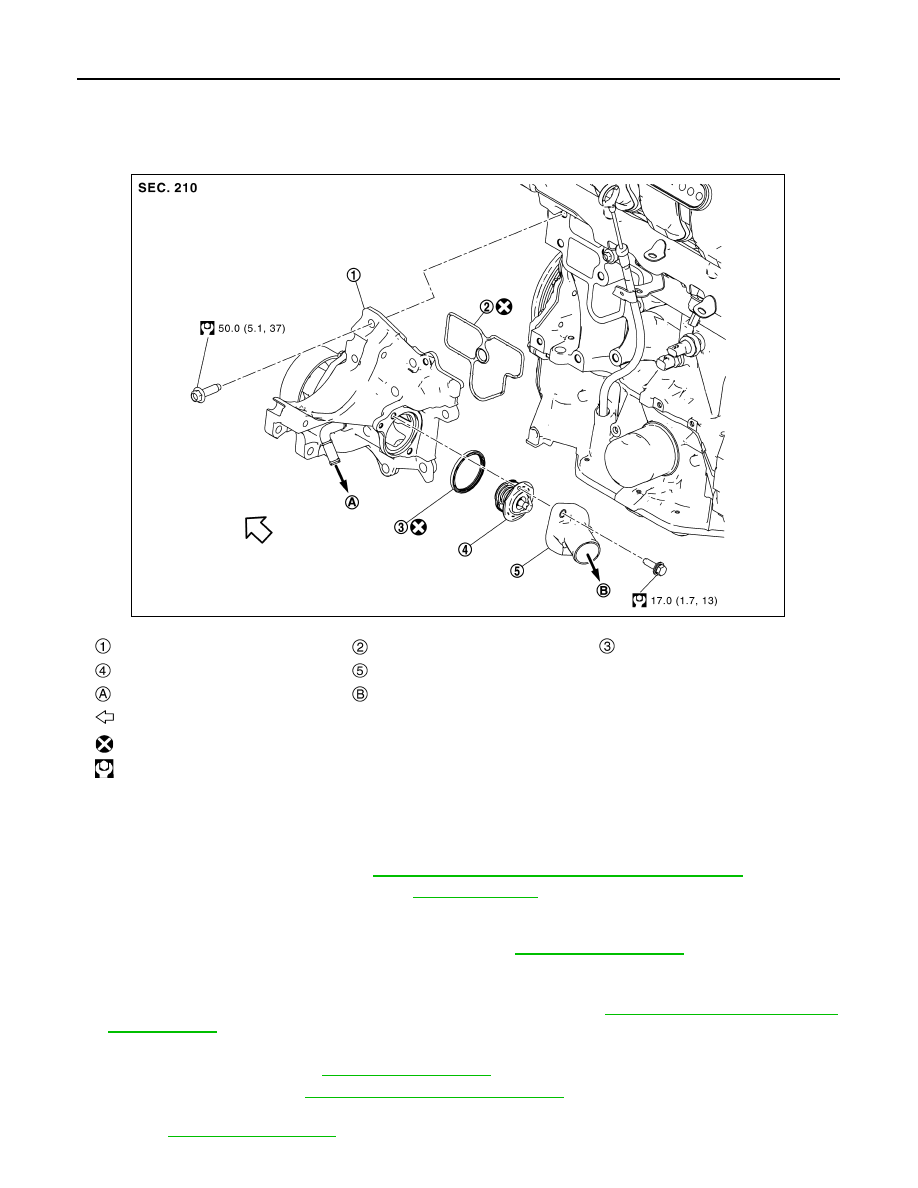
Exploded View
INFOID:0000000010782945
Removal and Installation
INFOID:0000000010782946
REMOVAL
1.
Remove engine under cover. Refer to
EXT-39, "ENGINE UNDER COVER : Exploded View"
2.
Drain engine coolant from radiator. Refer to
.
CAUTION:
Perform this step when engine is cold.
3.
Disconnect radiator hose (lower) from water inlet. Refer to
.
4.
Remove water inlet and thermostat.
• Engine coolant leakage from cylinder block, so have a receptacle ready below.
5.
Disconnect the battery cable from the negative terminal. Refer to
.
6.
Remove thermostat housing with the following procedure:
a.
Remove water pump. Refer to
.
b.
Remove alternator. Refer to
CHG-44, "MR20DD : Exploded View"
c.
Remove A/C compressor with A/C piping connected, and temporarily fasten it on vehicle with a rope.
Refer to
.
Thermostat housing
Gasket
Rubber ring
Thermostat
Water inlet
To oil cooler
To radiator
: Engine front
: Always replace after every disassembly.
: N·m (kg-m, ft-lb)
JSBIA4314GB