Nissan X-Trail 32. Manual - part 2239


  Главная      Nissan     Nissan X-Trail 32 - Service Manual


поиск по сайту            


содержание   ..  2237  2238  2239  2240   ..


Nissan X-Trail 32. Manual - part 2239


LIGHT & RAIN SENSOR

WW-63

< DTC/CIRCUIT DIAGNOSIS >

C

D

E

F

G

H

I

J

K

M

A

B

WW

N

O

P

Is the inspection result normal?

YES

>> Replace light & rain sensor.

NO

>> GO TO 9.

9.

CHECK LIGHT & RAIN SENSOR SIGNAL CIRCUIT

1.

Turn ignition switch OFF.

2.

Disconnect BCM connector and light & rain sensor connector.

3.

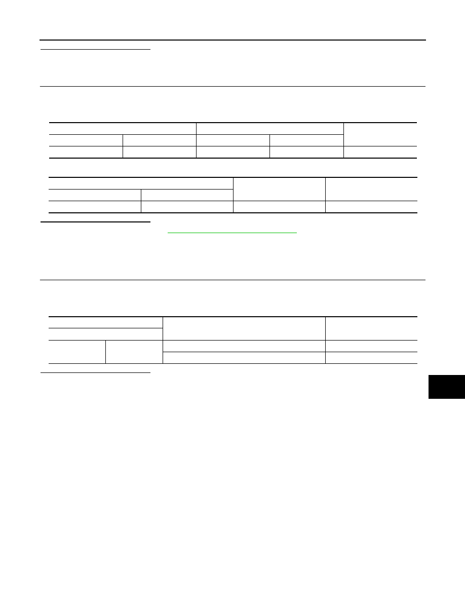
Check continuity between BCM harness connector and light & rain sensor harness connector.

4.

Check continuity between BCM harness connector and ground.

Is the inspection result normal?

YES

>> Replace BCM. Refer to 

BCS-121, "Removal and Installation"

.

NO

>> Repair or replace harness.

Component Inspection

INFOID:0000000010785436

1.

CHECK INTERIOR ROOM LAMP RELAY

1.

Turn ignition switch OFF.

2.

Remove interior room lamp relay.

3.

Check continuity between interior room lamp relay terminals.

Is the inspection result normal?

YES

>> INSPECTION END

NO

>> Replace interior room lamp relay.

BCM

Light & rain sensor

Continuity

Connector

Terminal

Connector

Terminal

M87

47

R20

2

Existed

BCM

Continuity

Connector

Terminal

M87

47

Ground

Existed

Interior room lamp relay

Condition

Continuity

Terminal

3

5

12 V direct current supply between terminals 1 and 2.

Existed

No current supply

Not existed

WW-64

< DTC/CIRCUIT DIAGNOSIS >

WASHER SWITCH

WASHER SWITCH

Component Inspection

INFOID:0000000010785437

1.

CHECK WASHER SWITCH

1.

Turn ignition switch OFF.

2.

Disconnect combination switch connector.

3.

Check continuity between the combination switch terminals.

Is the inspection result normal?

YES

>> INSPECTION END

NO

>> Replace combination switch.

Combination switch

Condition

Continuity

Terminal

14

11

Front washer switch ON

Existed

9

16

14

9

Rear washer switch ON

11

16

REAR WIPER MOTOR CIRCUIT

WW-65

< DTC/CIRCUIT DIAGNOSIS >

C

D

E

F

G

H

I

J

K

M

A

B

WW

N

O

P

REAR WIPER MOTOR CIRCUIT

Diagnosis Procedure

INFOID:0000000010785438

1.

CHECK REAR WIPER MOTOR OUTPUT VOLTAGE

1.

Turn rear wiper switch OFF, and wait for 1 minute or more. 

2.

Turn ignition switch OFF.

3.

Disconnect rear wiper motor connector.

4.

Turn ignition switch ON.

5.

With operating rear wiper switch, check voltage between rear wiper motor harness connector and ground.

*: When rear wiper motor connector is disconnected and rear wiper switch is ON for more than 5 seconds,
BCM stops the power supply according to rear wiper motor protection function. To perform the check again,
turn rear wiper switch OFF, wait for 1 minute or more, and then perform the check.

Is the inspection result normal?

YES

>> GO TO 3.

NO

>> GO TO 2.

2.

CHECK REAR WIPER MOTOR CIRCUIT

1.

Turn ignition switch OFF.

2.

Disconnect BCM connector.

3.

Check continuity between BCM harness connector and rear wiper motor harness connector.

4.

Check continuity between BCM harness connector and ground.

Is the inspection result normal?

YES

>> Replace BCM. Refer to 

BCS-121, "Removal and Installation"

.

NO

>> Repair or replace harness.

3.

CHECK REAR WIPER MOTOR GROUND OPEN CIRCUIT

Check continuity between rear wiper motor harness connector and ground.

Is the inspection result normal?

YES

>> Replace rear wiper motor.

NO

>> Repair or replace harness.

(+)

(

)

Condition

Voltage

Rear wiper motor

Connector

Terminal

D178

1

Ground

Rear wiper switch

ON

9 – 16 V

(5 seconds*)

BCM

Rear wiper motor

Continuity

Connector

Terminal

Connector

Terminal

B46

123

D178

1

Existed

BCM

Continuity

Connector

Terminal

B46

123

Ground

Not existed

Rear wiper motor

Continuity

Connector

Terminal

D178

3

Ground

Existed

WW-66

< DTC/CIRCUIT DIAGNOSIS >

REAR WIPER STOP POSITION SIGNAL CIRCUIT

REAR WIPER STOP POSITION SIGNAL CIRCUIT

Component Function Check

INFOID:0000000010785439

1.

CHECK REAR WIPER STOP POSITION SIGNAL

CONSULT DATA MONITOR

1.

Select “WIPER” of BCM data monitor item.

2.

Operate the rear wiper.

3.

Check that “RR WIPER STOP” changes to “On” and “Off” linked with the wiper operation.

Is the inspection result normal?

YES

>> Rear wiper stop position signal circuit is normal.

NO

>> Refer to 

WW-66, "Diagnosis Procedure"

.

Diagnosis Procedure

INFOID:0000000010785440

1.

CHECK REAR WIPER MOTOR (AUTO STOP) OUTPUT VOLTAGE

1.

Turn ignition switch OFF.

2.

Disconnect rear wiper motor connector.

3.

Turn ignition switch ON.

4.

Check voltage between rear wiper motor harness connector and ground.

Is the inspection result normal?

YES

>> Replace rear wiper motor.

NO

>> GO TO 2.

2.

CHECK REAR WIPER MOTOR (AUTO STOP) CIRCUIT

1.

Turn ignition switch OFF.

2.

Disconnect BCM connector.

3.

Check continuity between BCM harness connector and rear wiper motor harness connector.

4.

Check continuity between rear wiper motor harness connector and ground.

Is the inspection result normal?

Monitor item

Condition

Monitor status

RR WIPER STOP

Rear wiper motor

Stop position

Off

Except stop position

On

(+)

(

)

Voltage

Rear wiper motor

Connector

Terminal

D178

2

Ground

JMMIA1654GB

BCM 

Rear wiper motor

Continuity

Connector

Terminal

Connector

Terminal

B47

15

D178

2

Existed

Rear wiper motor

Continuity

Connector

Terminal

D178

2

Ground

Not existed


содержание   ..  2237  2238  2239  2240   ..