содержание .. 2234 2235 2236 2237 ..
Nissan X-Trail 32. Manual - part 2236
DIAGNOSIS AND REPAIR WORK FLOW
WW-51
< BASIC INSPECTION >
C
D
E
F
G
H
I
J
K
M
A
B
WW
N
O
P
BASIC INSPECTION
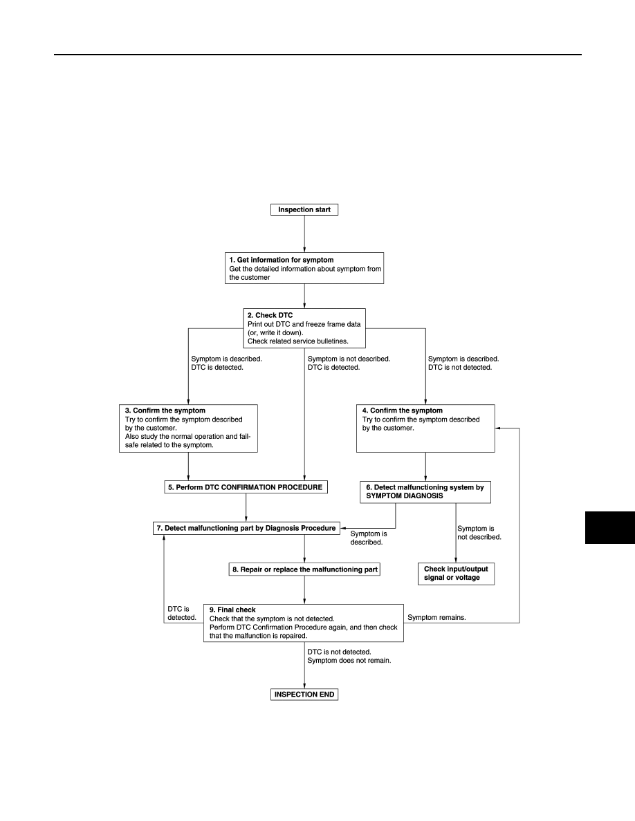
DIAGNOSIS AND REPAIR WORK FLOW
Work Flow
INFOID:0000000010785426
OVERALL SEQUENCE
DETAILED FLOW
JMKIA8652GB