Nissan X-Trail 32. Manual - part 1991


  Главная      Nissan     Nissan X-Trail 32 - Service Manual


поиск по сайту            


содержание   ..  1989  1990  1991  1992   ..


Nissan X-Trail 32. Manual - part 1991


STC-14

< SYSTEM DESCRIPTION >

SYSTEM

• Also turns ON when ignition switch is turned ON, for purpose of lamp check. Turns OFF after the engine

starts, if system is normal.

CAUTION:

Electric power steering warning lamp also turns ON due to data reception error, CAN communication
error etc.

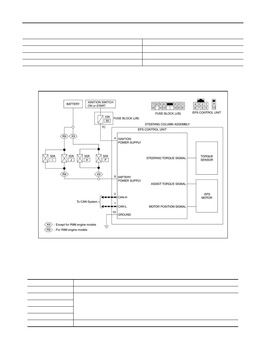
EPS SYSTEM : Circuit Diagram

INFOID:0000000010688403

EPS SYSTEM : Fail-Safe

INFOID:0000000010699143

• If any malfunction occurs in the system and control unit detects the malfunction, Electric power steering

warning lamp on combination meter turns ON to indicate system malfunction.

• When Electric power steering warning lamp is ON, the system enters into a manual steering state. (Control

turning force steering wheel becomes heavy.)

Condition

Electric power steering warning lamp

Ignition switch ON. (Lamp check)

ON

Engine running.

OFF

EPS system malfunction [Other diagnostic item]

ON

JSGIA1568GB

DTC

Fail-safe condition

C1601

Assist is reduced according to voltage, resulting in manual steering state.

C1604

Manual steering state.

C1606

C1607

C1608

C1609

Constant steering assist level state

SYSTEM

STC-15

< SYSTEM DESCRIPTION >

C

D

E

F

H

I

J

K

L

M

A

B

STC

N

O

P

EPS SYSTEM : Protection Function

INFOID:0000000010699144

EPS control unit decreases the output signal to EPS motor while extremely using the power steering function
(e.g., full steering) consecutively for protecting EPS motor and EPS control unit (Overload protection control).
While activating overload protection control, the assist torque gradually decreases, and the steering wheel
turning force becomes heavy. The normal assist torque is recovered if the steering wheel is not turned for a
while.

WARNING/INDICATOR/CHIME LIST

WARNING/INDICATOR/CHIME LIST : Warning Lamp/Indicator Lamp

INFOID:0000000010688406

U1000

Normal control
NOTE:
If the cause is in a different ECU, the state changes to fixed steering assist force.

U1010

Normal control

U1970

Around view monitor with park assist function stops (controlled by around view monitor).

U1971

Around view monitor with park assist function stops (controlled by sonar).

DTC

Fail-safe condition

Name

Design

Layout/Function

Electric power steer-
ing warning lamp

For layout, refer to 

MWI-10, "METER SYSTEM : Design"

.

For function, refer to 

MWI-35, "WARNING LAMPS/INDICATOR LAMPS : Electric Power Steer-

ing Warning Lamp"

.

STC-16

< SYSTEM DESCRIPTION >

DIAGNOSIS SYSTEM (EPS CONTROL UNIT)

DIAGNOSIS SYSTEM (EPS CONTROL UNIT)

CONSULT Function

INFOID:0000000010688407

FUNCTION

CONSULT can display each diagnostic item using the diagnostic test modes shown following.

*: The following diagnosis information is erased by erasing.
• DTC
• Freeze frame data (FFD)

ECU IDENTIFICATION

Displays the part number stored in the control unit.

SELF-DIAG RESULTS MODE

Refer to 

STC-21, "DTC Index"

.

When “CRNT” is displayed on self-diagnosis result.

• The system is presently malfunctioning.

When “PAST” is displayed on self-diagnosis result.

• System malfunction in the past is detected, but the system is presently normal.

FREEZE FRAME DATA (FFD)

The following vehicle status is recorded when DTC is detected and is displayed on CONSULT.

DATA MONITOR MODE

NOTE:
The following table includes information (items) inapplicable to this vehicle. For information (items) applicable
to this vehicle, refer to CONSULT display items.

Diagnostic test mode

Function

ECU identification

The part number stored in the control unit can be read.

Self diagnostic result

Self-diagnostic results and freeze frame data can be read and erased quickly.

*

Data monitor

Input/Output data in the EPS control unit can be read.

Item name

Display item

IGN COUNTER
(0 – 39)

The number of times that ignition switch is turned ON after the DTC is detected is displayed.
• When “0” is displayed: It indicates that the system is presently malfunctioning.
• When except “0” is displayed: It indicates that system malfunction in the past is detected, but the system is pres-

ently normal.
NOTE:
Each time when ignition switch is turned OFF to ON, numerical number increases in 1

2

3...38

39.

When the operation number of times exceeds 39, the number do not increase and “39” is displayed until self-
diagnosis is erased.

Monitor item (Unit)

Remarks

BATTERY VOLT (V)

Displays the power supply voltage for EPS control unit.

TORQUE SENSOR (Nm)

Displays steering wheel turning force detected by torque sensor.

MOTOR CURRENT (A)

Displays the current value consumed by EPS motor.

*1

MOTOR SIG (A)

Displays the current commanded value to EPS motor.

ASSIST TORQUE (Nm)

Displays assist torque of EPS motor being output by the electric power steering.

C/U TEMP (

°

C) or (

°

F)

Displays the temperature of the EPS control unit.

ASSIST LEVEL (%)

Normally displays 100%. In case of an excessive stationary steering, the assist 

curvature gradually falls. However, it return to 100% when left standing.

*2

VEHICLE SPEED (km/h) or (MPH)

Vehicle speed is displayed from vehicle speed signal via CAN communication.

*3

WARNING LAMP (On/Off)

EPS warning lamp control status is displayed.

ENGINE STATUS (Stop/Run)

Engine speed is displayed from engine status signal via CAN communication.

DIAGNOSIS SYSTEM (EPS CONTROL UNIT)

STC-17

< SYSTEM DESCRIPTION >

C

D

E

F

H

I

J

K

L

M

A

B

STC

N

O

P

*1: Almost in accordance with the value of “MOTOR SIG”. It is not a malfunction though these values are not
accorded when steering quickly.
*2: Normally displays 100%. In case of an excessive stationary steering, the assist curvature gradually falls.
However, it returns to 100% when left standing.
*3: It is not a malfunction, though it might not be corresponding just after ignition switch in turned ON.

ST TORQUE STATUS (On/Off)

Displays the operating state of steering wheel.

EPS ASSIST PERMIS (On/Off)

Displays assist permission status of EPS system.

STOP/START STATUS (INACT/AUTO ST/ACT/
CANCEL)

Displays stop/start status.

IPA ON (Off1/Off2/Off3/On)

Displays the status of around view monitor with park assist.

IPA STATUS 1 (On/Off)

Displays the operating state of around view monitor with park assist.

STOP/START SYSTEM (On/Off)

Displays permission status of stop/start system.

IPA STATUS 2 (Off/On1/On2/On3)

Displays the operating state of around view monitor with park assist.

IPA STATUS 3 (NORMAL/MALF)

Displays the status of around view monitor with park assist.

IPA TARGET CURRENT (A)

Displays a command current value from around view monitor with park assist.

EPS CONTROL CURRENT (A)

Displays a current value of motor.

Monitor item (Unit)

Remarks


содержание   ..  1989  1990  1991  1992   ..