Nissan X-Trail 32. Manual - part 1943


  Главная      Nissan     Nissan X-Trail 32 - Service Manual


поиск по сайту            


содержание   ..  1941  1942  1943  1944   ..


Nissan X-Trail 32. Manual - part 1943


SN-228

< DTC/CIRCUIT DIAGNOSIS >

[WITH PARK ASSIST]

B272F-14 SIDE SENSOR [FR]

Is the inspection result normal?

YES

>> GO TO 3.

NO

>> Repair or replace malfunctioning parts.

3.

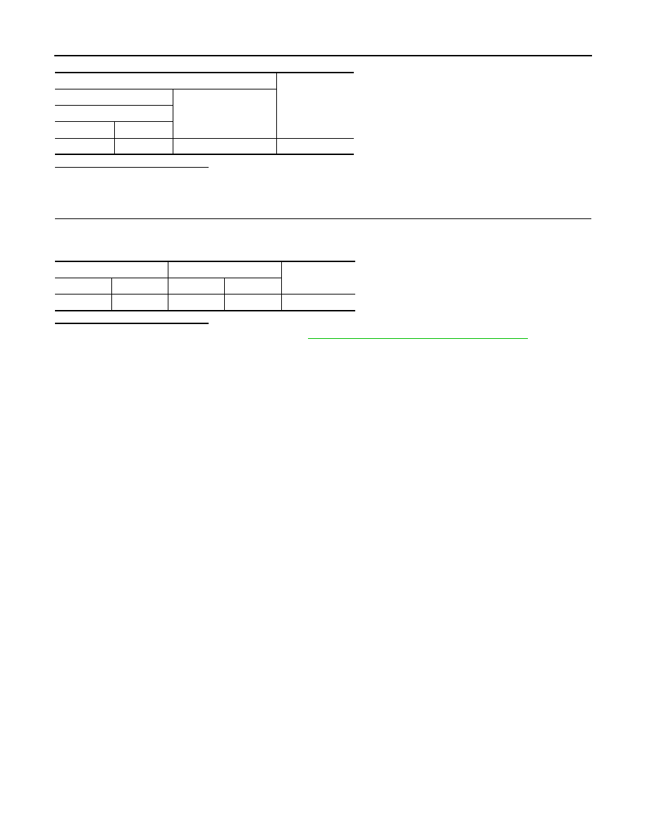
CHECK FRONT SENSOR GROUND CIRCUIT

Check the continuity between sonar control unit harness connector and side sensor front RH harness connec-
tor.

Is the inspection result normal?

YES

>> Replace side sensor front RH. Refer to 

SN-239, "FRONT : Removal and Installation"

.

NO

>> Repair or replace malfunctioning parts.

Terminals

Continuity

(+)

(

)

Sonar control unit

Connector

Terminal

B128

39

Ground

Not existed

Sonar control unit

Side sensor front RH

Continuity

Connector

Terminal

Connector

Terminal

B128

36

E172

3

Existed

SN

B272F-55 SIDE SENSOR [FR]

SN-229

< DTC/CIRCUIT DIAGNOSIS >

[WITH PARK ASSIST]

C

D

E

F

G

H

I

J

K

L

M

B

A

O

P

B272F-55 SIDE SENSOR [FR]

DTC Description

INFOID:0000000010777013

DTC DETECTION LOGIC

POSSIBLE CAUSE

• Side sensor front RH
• Control unit setting of sonar control unit is incomplete

FAIL-SAFE

• Obstacle detection function is stopped
• Alarm display is displayed on the information display of combination meter 

DTC CONFIRMATION PROCEDURE

1.

PERFORM DTC CONFIRMATION PROCEDURE

With CONSULT

1.

Turn ignition switch ON.

2.

Turn ignition switch OFF and wait at least 30 seconds.

3.

Turn ignition switch ON and wait at least 30 seconds or more.

4.

Select “Self Diagnostic Result” mode of “SONAR” using CONSULT.

5.

Check DTC.

Is DTC B272F-55 detected?

YES

>> Proceed to 

SN-229, "Diagnosis Procedure"

.

NO-1

>> To check malfunction symptom before repair: Refer to 

GI-44, "Intermittent Incident"

.

NO-2

>> Confirmation after repair: INSPECTION END

Diagnosis Procedure

INFOID:0000000010777014

1.

PERFORM CONFIGURATION OF SONAR CONTROL UNIT

Perform configuration of sonar control unit. Refer to 

SN-156, "CONFIGURATION (SONAR CONTROL UNIT) :

Work Procedure"

.

>> GO TO 2.

2.

PERFORM DTC CONFIRMATION PROCEDURE AGAIN

Perform DTC confirmation procedure again. Refer to 

SN-229, "DTC Description"

.

Is DTC B272F-55 detected again?

YES

>> Replace side sensor front RH. Refer to 

SN-239, "FRONT : Removal and Installation"

.

NO

>> INSPECTION END.

DTC

Trouble diagnosis

(Trouble diagnosis contents)

Detecting condition

B272F-55

SIDE SENSOR [FR]
(Side sensor front-right)

CONFIG ERROR
(Configuration er-
ror)

Control unit setting of sonar control unit is incomplete or is not set 
normally.

SN-230

< DTC/CIRCUIT DIAGNOSIS >

[WITH PARK ASSIST]

B272F-92 SIDE SENSOR [FR]

B272F-92 SIDE SENSOR [FR]

DTC Description

INFOID:0000000010777015

DTC DETECTION LOGIC

POSSIBLE CAUSE

• Side sensor front RH

FAIL-SAFE

• Obstacle detection function is stopped
• Alarm display is displayed on the information display of combination meter 

DTC CONFIRMATION PROCEDURE

1.

PERFORM DTC CONFIRMATION PROCEDURE

With CONSULT

1.

Turn ignition switch ON.

2.

Turn ignition switch OFF and wait at least 30 seconds.

3.

Turn ignition switch ON and wait at least 30 seconds or more.

4.

Select “Self Diagnostic Result” mode of “SONAR” using CONSULT.

5.

Check DTC.

Is DTC B272F-92 detected?

YES

>> Proceed to 

SN-230, "Diagnosis Procedure"

.

NO-1

>> To check malfunction symptom before repair: Refer to 

GI-44, "Intermittent Incident"

.

NO-2

>> Confirmation after repair: INSPECTION END

Diagnosis Procedure

INFOID:0000000010777016

1.

PERFORM DTC CONFIRMATION PROCEDURE AGAIN

With CONSULT

1.

Turn ignition switch ON.

2.

Erase DTC.

3.

Perform DTC confirmation procedure again. Refer to 

SN-230, "DTC Description"

.

Is DTC B272F-92 detected again?

YES

>> Replace side sensor front RH. Refer to 

SN-239, "FRONT : Removal and Installation"

.

NO

>> INSPECTION END

DTC

Trouble diagnosis

(Trouble diagnosis contents)

Detecting condition

B272F-92

SIDE SENSOR [FR]
(Side sensor front-right)

SENSOR
(Sensor)

Side sensor front RH malfunction is detected when ignition switch is 
turned ON.

SN

U1000-01 CAN COMM CIRCUIT

SN-231

< DTC/CIRCUIT DIAGNOSIS >

[WITH PARK ASSIST]

C

D

E

F

G

H

I

J

K

L

M

B

A

O

P

U1000-01 CAN COMM CIRCUIT

DTC Description

INFOID:0000000010736695

DESCRIPTION

CAN (Controller Area Network) is a serial communication line for real-time application. It is an on-vehicle mul-
tiplex communication line with high data communication speed and excellent error detection ability. Many elec-
tronic control units are equipped onto a vehicle, and each control unit shares information and links with other
control units during operation (not independently). In CAN communication, control units are connected with 2
communication lines (CAN-H, CAN-L) allowing a high rate of information transmission with less wiring. Each
control unit transmits/receives data but selectively reads required data only.
CAN Communication Signal Chart. Refer to 

LAN-41, "CAN COMMUNICATION SYSTEM : CAN Communica-

tion Signal Chart"

.

DTC DETECTION LOGIC

POSSIBLE CAUSE

CAN communication system

FAIL-SAFE

• Obstacle detection function is stopped
• Alarm display is displayed on the information display of combination meter 

DTC CONFIRMATION PROCEDURE

1.

PERFORM DTC CONFIRMATION PROCEDURE

With CONSULT

1.

Turn ignition switch ON.

2.

Turn ignition switch OFF and wait at least 30 seconds.

3.

Turn ignition switch ON and wait at least 2 seconds or more.

4.

Select “Self Diagnostic Result” mode of “SONAR” using CONSULT.

5.

Check DTC.

Is DTC U1000 detected?

YES

>> Proceed to 

SN-231, "Diagnosis Procedure"

.

NO-1

>> To check malfunction symptom before repair: Refer to 

GI-44, "Intermittent Incident"

.

NO-2

>> Confirmation after repair: INSPECTION END

Diagnosis Procedure

INFOID:0000000010736696

1.

PERFORM DTC CONFIRMATION PROCEDURE AGAIN

With CONSULT

1.

Turn ignition switch ON.

2.

Erase DTC.

3.

Perform DTC confirmation procedure again. Refer to 

SN-231, "DTC Description"

.

Is DTC U1000 detected again?

YES

>> Perform the trouble diagnosis for CAN communication system. Refer to 

LAN-17, "Trouble Diagno-

sis Flow Chart"

.

NO

>> INSPECTION END

DTC

Trouble diagnosis

(Trouble diagnosis contents)

Detecting condition

U1000

CAN COMM CIRCUIT
(CAN communication circuit)

Sonar control unit is not transmitting or receiving CAN communication signal for 
2 seconds or more.


содержание   ..  1941  1942  1943  1944   ..