содержание .. 1938 1939 1940 1941 ..
Nissan X-Trail 32. Manual - part 1940
SN-216
< DTC/CIRCUIT DIAGNOSIS >
[WITH PARK ASSIST]
B272D-12 FRONT BUZZER
Is the inspection result normal?
YES
>> Replace buzzer (frontward). Refer to
SN-242, "FRONT : Removal and Installation"
NO
>> Repair harness or connector.
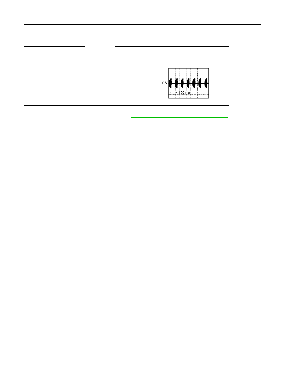
Sonar control unit
Ground
Standard
Reference value
(Approx.)
Connector
Terminal
B129
10
—
NOTE:
• Voltage depends on volume.
• Cycle depends on distance between sensor
and obstacle.
JSNIA5232GB