содержание .. 1871 1872 1873 1874 ..
Nissan X-Trail 32. Manual - part 1873
DIAGNOSIS AND REPAIR WORK FLOW
SEC-259
< BASIC INSPECTION >
[WITHOUT INTELLIGENT KEY SYSTEM]
C
D
E
F
G
H
I
J
L
M
A
B
SEC
N
O
P
BASIC INSPECTION
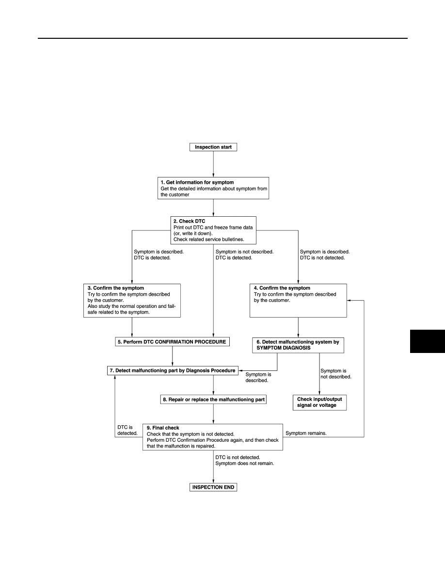
DIAGNOSIS AND REPAIR WORK FLOW
Work Flow
INFOID:0000000010922273
OVERALL SEQUENCE
DETAILED FLOW
JMKIA8652GB