содержание .. 1810 1811 1812 1813 ..
Nissan X-Trail 32. Manual - part 1812
SYSTEM
SEC-15
< SYSTEM DESCRIPTION >
[WITH INTELLIGENT KEY SYSTEM]
C
D
E
F
G
H
I
J
L
M
A
B
SEC
N
O
P
SYSTEM
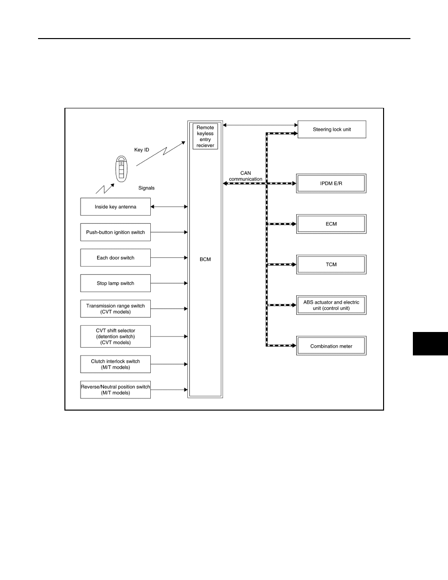
INTELLIGENT KEY SYSTEM/ENGINE START FUNCTION
INTELLIGENT KEY SYSTEM/ENGINE START FUNCTION : System Description
INFOID:0000000010922116
SYSTEM DIAGRAM
BCM INPUT/OUTPUT SIGNAL CHART
Input Signal Item
JMKIB3758GB