Nissan X-Trail 32. Manual - part 1772


  Главная      Nissan     Nissan X-Trail 32 - Service Manual


поиск по сайту            


содержание   ..  1770  1771  1772  1773   ..


Nissan X-Trail 32. Manual - part 1772


RSU-10

< REMOVAL AND INSTALLATION >

COIL SPRING

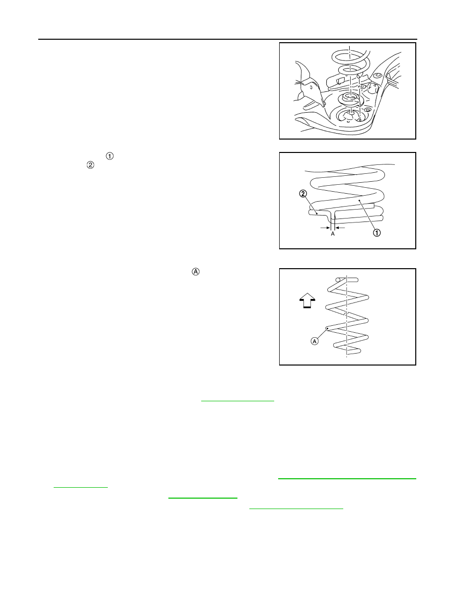
• Securely install coil spring with the lower end aligned with the

steps of lower rubber seat.

CAUTION:

The lower rubber seat protrusion must be securely inserted
into the hole of rear suspension arm.

• Install coil spring 

 by aligning lower end of coil spring with lower

rubber seat 

 as shown in the figure.

CAUTION:

Set coil spring so that its paint mark 

 is aligned with the

position of 1.75 turns from the bottom end of the coil spring. 

• Perform final tightening of fixing parts at the vehicle installation position (rubber bushing), under unladen

conditions with tires on level ground.

• Perform inspection after installation. Refer to 

RSU-10, "Inspection"

.

Inspection

INFOID:0000000010822780

INSPECTION AFTER REMOVAL

Check rear lower link, rubber seat, upper seat, and coil spring for deformation, crack, and damage. Replace it
if necessary.

INSPECTION AFTER INSTALLATION

1.

Check wheel sensor harness for proper connector. Refer to 

BRC-213, "REAR WHEEL SENSOR :

Exploded View"

.

2.

Check wheel alignment. Refer to 

RSU-7, "Inspection"

.

3.

Adjust neutral position of steering angle sensor. Refer to 

BRC-99, "Work Procedure"

.

SEIA0636J

Dimension (A)

: 5 mm (0.20 in) or less

JSEIA0671ZZ

ALEIA0210ZZ

REAR SHOCK ABSORBER

RSU-11

< REMOVAL AND INSTALLATION >

C

D

F

G

H

I

J

K

L

M

A

B

RSU

N

O

P

REAR SHOCK ABSORBER

Exploded View

INFOID:0000000010822781

Removal and Installation

INFOID:0000000010822782

REMOVAL

1.

Remove tires. Refer to 

WT-61, "Removal and Installation"

.

2.

Set jack (A) under suspension arm to relieve the coil spring tension.

CAUTION:

• Check the stable condition when using a jack.
• Never damage suspesion arm with a jack.

3.

Remove shock absorber mounting bolt (Upper and lower side).

4.

Remove shock absorber.

5.

Perform inspection after removal. Refer to 

RSU-11, "Inspection"

.

INSTALLATION

Note the following, and install in the reverse order of removal.
• Perform final tightening of fixing parts at the vehicle installation position (rubber bushing), under unladen

conditions with tires on level ground.

• Perform inspection after installation. Refer to 

RSU-11, "Inspection"

.

• After replacing the shock absorber, always follow the disposal procedure to discard the shock absorber.

Refer to 

RSU-12, "Disposal"

.

Inspection

INFOID:0000000010822783

INSPECTION AFTER DISASSEMBLY

Check the following items, and replace the part if necessary.
• Shock absorber for deformation, cracks, and other damage.
• Piston rod for damage, uneven wear, and distortion.
• Oil leakage

INSPECTION AFTER INSTALLATION

1.

Check wheel alignment. Refer to 

RSU-7, "Inspection"

.

Rear suspension member

shock absorber

Suspension arm

: N·m (kg-m, ft-lb)

: Vehicle front

JSEIA0904GB

RSU-12

< REMOVAL AND INSTALLATION >

REAR SHOCK ABSORBER

2.

Adjust neutral position of steering angle sensor. Refer to 

BRC-99, "Work Procedure"

.

Disposal

INFOID:0000000010822784

1.

Set shock absorber horizontally to the ground with the piston rod fully extracted.

2.

Drill 2 – 3 mm (0.08 – 0.12 in) hole at the position (

) from top

as shown in the figure to release gas gradually.

CAUTION:

• Wear eye protection (safety glasses).
• Wear gloves.
• Be careful with metal chips or oil blown out by the com-

pressed gas.

NOTE:
• Drill vertically in this direction show by arrow.
• Directly to the outer tube avoiding brackets.
• The gas is clear, colorless, odorless, and harmless.

3.

Position the drilled hole downward and drain oil by moving the piston rod several times.

CAUTION:

Dispose of drained oil according to the law and local regulations.

A

: 20 – 30 mm (0.79 – 1.18 in)

JPEIA0161ZZ

REAR SUSPENSION ARM

RSU-13

< REMOVAL AND INSTALLATION >

C

D

F

G

H

I

J

K

L

M

A

B

RSU

N

O

P

REAR SUSPENSION ARM

Exploded View

INFOID:0000000010822785

Removal and Installation

INFOID:0000000010822786

REMOVAL

1.

Remove tires. Refer to 

WT-61, "Removal and Installation"

.

2.

Drain brake fluid.
• LHD: Refer to 

BR-13, "Draining"

.

• RHD: Refer to 

BR-77, "Draining"

.

3.

Remove wheel sensor and sensor harness. Refer to 

BRC-214, "REAR WHEEL SENSOR : Removal and

Installation"

.

4.

Remove caliper assembly. Hang caliper assembly in a place where it will not interfere with work.
• LHD: Refer to 

BR-63, "BRAKE CALIPER ASSEMBLY : Removal and Installation"

.

• RHD: Refer to 

BR-123, "BRAKE CALIPER ASSEMBLY : Removal and Installation"

.

CAUTION:

Never depress brake pedal while brake caliper is removed.

5.

Remove disc rotor.
• 2WD: Refer to 

RAX-7, "Removal and Installation"

.

• 4WD: Refer to 

RAX-18, "Removal and Installation"

.

CAUTION:

• Put matching marks on the wheel hub assembly and the disc rotor before removing the disc

rotor.

• Never drop disc rotor.

6.

Remove parking brake cable mounting bolt. Refer to 

PB-154, "Exploded View"

.

7.

Separate the brake tube from the brake hose, and then remove rock plate.
• LHD: Refer to 

BR-29, "REAR : Removal and Installation"

.

• RHD: Refer to 

BR-92, "REAR : Removal and Installation"

.

8.

Remove brake tube from suspension arm. 
• LHD: Refer to 

BR-27, "REAR : Exploded View"

.

Suspension arm bracket

Suspension bar

Arm stopper

Suspension arm

: Always replace after every disassembly.

: N·m (kg-m, ft-lb)

: Vehicle front

JSEIA0906GB


содержание   ..  1770  1771  1772  1773   ..