содержание .. 1741 1742 1743 1744 ..
Nissan X-Trail 32. Manual - part 1743
PWC-74
< REMOVAL AND INSTALLATION >
FRONT POWER WINDOW SWITCH
REMOVAL AND INSTALLATION
FRONT POWER WINDOW SWITCH
POWER WINDOW MAIN SWITCH
POWER WINDOW MAIN SWITCH : Removal and Installation
INFOID:0000000010735257
CAUTION:
Never bend the pawl of power window main switch finisher.
REMOVAL
1.
Disconnect the battery negative terminal. Refer to
PG-142, "EXCEPT FOR R9M : Removal and Installa-
2.
Remove power window main switch finisher. Refer to
INT-14, "Removal and Installation"
.
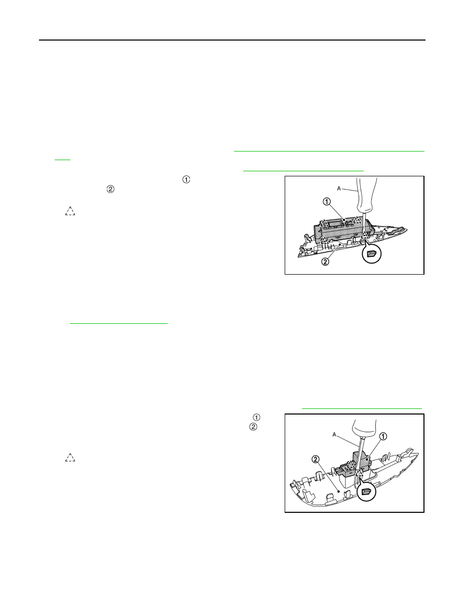
3.
Remove power window main switch
from power window main
switch finisher
using remover tool (A).
INSTALLATION
Install in the reverse order of removal.
NOTE:
If power window main switch is replaced or is removed, it is necessary to perform the initialization procedure.
Refer to
FRONT POWER WINDOW SWITCH (PASSENGER SIDE)
FRONT POWER WINDOW SWITCH (PASSENGER SIDE) : Removal and Installation
INFOID:0000000010735258
CAUTION:
Never bend the pawl of front power window switch (passenger side) finisher.
REMOVAL
1.
Remove front power window switch (passenger side) finisher. Refer to
INT-14, "Removal and Installation"
.
2.
Remove front power window switch (passenger side)
from
front power window switch (passenger side) finisher
using
remover tool (A).
INSTALLATION
Install in the reverse order of removal.
: Pawl
JMKIB3544ZZ
: Pawl
JMKIB3545ZZ