Nissan X-Trail 32. Manual - part 1624


  Главная      Nissan     Nissan X-Trail 32 - Service Manual


поиск по сайту            


содержание   ..  1622  1623  1624  1625   ..


Nissan X-Trail 32. Manual - part 1624


PB-22

< SYSTEM DESCRIPTION >

SYSTEM

• When parking brake switch is pulled/pushed during system malfunction, electric parking brake indicator

lamp blinks and master warning lamp (red) turns ON when electric parking brake cannot be operated. It
restricts braking and release operations of electric parking brake. 
NOTE:
The parking brake can be mechanically released.
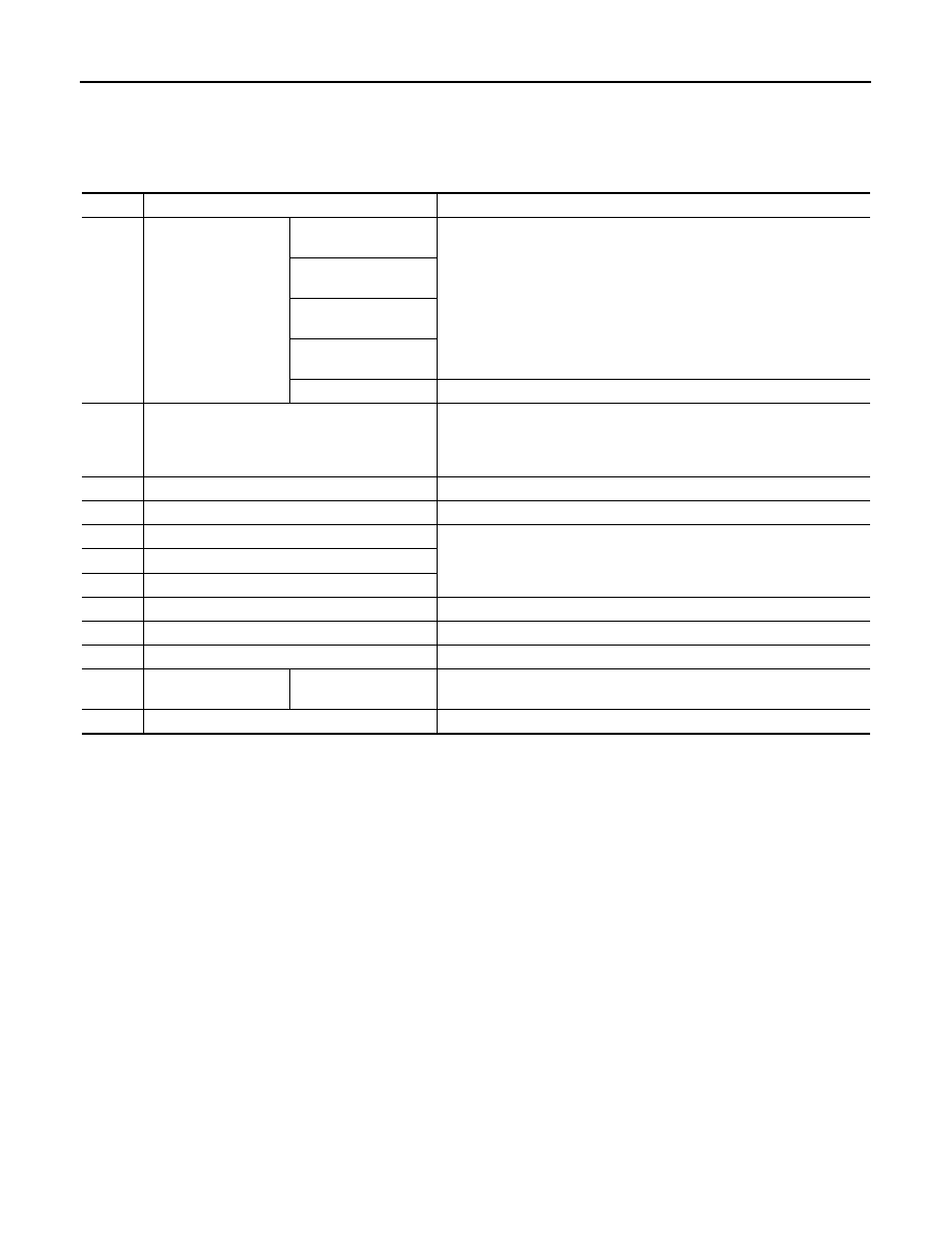
DTC

Display item

Vehicle condition

C10C8

CONTROL MODULE

[INTERNAL ELEC-
TRIC MALFUNCTION]

Only mechanical release is available.

[WATCHDOG/SAFET-
Y

µ

C ERROR]

[SUPERVISION 
SOFTWARE ERROR]

[EVENT INFORMA-
TION]

[NOT CONFIGURED]

Automatic apply and release are prohibited.

C10E3

PARKING BRAKE SWITCH

• Applying the parking brake is prohibited.
• Release using the parking brake switch is prohibited. (It can be re-

leased automatically.)

• Automatic apply is available.

C10E6

IGNITION SWITCH

Normal control

C1BD0

MOTOR

One side motor is available.

C1BD1

PARKING BRAKE SW

• Apply and release by switch are prohibited.
• Automatic apply and release are available.

C1BD2

PARKING BRAKE SW

C1BD3

PARKING BRAKE SW

C1BD4

G SENSOR

Automatic release is prohibited.

C1BD5

POWER SUPPLY VOLT

Only mechanical release is available.

C1BD6

DOOR SW

Normal control

C1BD7

CLUTCH SENSOR

[WRONG MOUNTING]

Automatic apply and release are prohibited. (Manual release can be per-
formed.)

C1BD9

INITIALIZE POSITION

Automatic apply and release are prohibited.

SYSTEM

PB-23

< SYSTEM DESCRIPTION >

C

D

E

G

H

I

J

K

L

M

A

B

PB

N

O

P

WARNING/INDICATOR/CHIME LIST

WARNING/INDICATOR/CHIME LIST : Warning Lamp/Indicator Lamp

INFOID:0000000010722924

C1BDA

ACTUATOR MALF 
(LH)

[MECHANICAL MAL-
FUNCTION]

Other side actuator’s apply and release are available.

[COMMAND POSI 
NOT REACHABLE]

[PFM/INCORRECT 
OPERATION]

[CIRC CRRNT BE-
LOW THRESHLD]

[CIRC CRRNT ABOVE 
THRESHOLD]

[CIRC CURRENT OUT 
OF RANGE]

C1BDB

ACTUATOR MALF 
(RH)

[MECHANICAL MAL-
FUNCTION]

[COMMAND POSI 
NOT REACHABLE]

[PFM/INCORRECT 
OPERATION]

[CIRC CRRNT BE-
LOW THRESHLD]

[CIRC CRRNT ABOVE 
THRESHOLD]

[CIRC CURRENT OUT 
OF RANGE]

C1BDF

MODE

Automatic apply and release are prohibited.

U0100

ECM/PCM A

U0101

TCM

Automatic release is prohibited.

U0111

BATTERY ENERGY CONTROL MODULE A

Automatic apply and release are prohibited.

U0129

BRAKE SYSTEM CONTROL MODULE

• Automatic apply and release are prohibited.
• Brake force is degraded.

U0140

BCM

Automatic apply and release are prohibited.

U0155

IPC CONTROL MODULE

Automatic release is prohibited.

U0401

VCM

Automatic apply and release are prohibited.

U0402

TCM

Automatic release is prohibited.

U0418

BRAKE CONTROL MODULE

• Automatic apply and release are prohibited.
• Brake force is degraded.

U0422

BCM

Automatic release is prohibited.

U1000

CAN COMM CIRCUIT

[BUS OFF]

• Automatic apply and release are prohibited.
• Brake force is degraded.

[ERRATIC]

U1060

VEHICLE SPEED

U1061

IPDM E/R SYSTEM

Automatic release is prohibited.

DTC

Display item

Vehicle condition

Name

Design

Layout/Function

Electric parking 
brake indicator lamp

For layout: Refer to 

MWI-10, "METER SYSTEM : Design"

.

For function: Refer to 

MWI-33, "WARNING LAMPS/INDICATOR LAMPS : Electric Parking Brake 

Indicator Lamp"

.

PB-24

< SYSTEM DESCRIPTION >

SYSTEM

INFORMATION DISPLAY (COMBINATION METER)

INFORMATION DISPLAY (COMBINATION METER) : Parking Brake Warning

INFOID:0000000010722925

DESIGN/PURPOSE

• Warns the driver of the necessity of depressing the brake pedal.
• Warns the driver of the necessity of releasing the parking brake.

Warning Message

SYNCHRONIZATION WITH MASTER WARNING LAMP

Applicable
Refer to 

MWI-47, "WARNING LAMPS/INDICATOR LAMPS : Master Warning Lamp"

.

SYNCHRONIZATION WITH WARNING CHIME

Applicable
Refer to 

PB-13, "System Description"

.

SYSTEM DIAGRAM

SIGNAL PATH

The electric parking brake control module transmits a signal to the combination meter via CAN communication
under the conditions bellow:
• When necessary to depress the brake pedal.
• When necessary to release the parking brake.

WARNING/INDICATOR OPERATING CONDITION

When the following conditions are satisfied (ignition switch ON)
• The parking brake switch is pushed without depressing the brake pedal.
• The automatic release is applied during driving by depressing the accelerator pedal with the seat belt unfas-

tened, and the engine running.

• The vehicle is driven by depressing the accelerator pedal without the automatic release applied, the seat

belt unfastened, and the engine running.

• The parking brake is operated with the parking brake switch kept pulled during driving.
• The parking brake braking force is insufficient (vehicle is moving backward).
• The parking brake does not operate automatically even after the ignition switch turned OFF.
• When trying to get off the vehicle.
• When the vehicle is moving.

Brake system warn-
ing lamp (yellow)

For layout: Refer to 

MWI-10, "METER SYSTEM : Design"

.

For function: Refer to 

MWI-28, "WARNING LAMPS/INDICATOR LAMPS : Brake System Warning 

Lamp (Yellow)"

.

Name

Design

Layout/Function

Design

Warning Message

Press brake pedal
Release parking brake

JSFIA2492GB

DIAGNOSIS SYSTEM (ELECTRIC PARKING BRAKE CONTROL MODULE)

PB-25

< SYSTEM DESCRIPTION >

C

D

E

G

H

I

J

K

L

M

A

B

PB

N

O

P

DIAGNOSIS SYSTEM (ELECTRIC PARKING BRAKE CONTROL MODULE)

CONSULT Function

INFOID:0000000010722926

APPLICATION ITEM

CONSULT can display each diagnostic item using the diagnostic test modes as follows.

*

: The following diagnosis information is erased by erasing.

• DTC
• Freeze frame data (FFD)

ECU IDENTIFICATION

Electric parking brake control module part number can be read.

SELF DIAGNOSTIC RESULT

Refer to 

PB-36, "DTC Index"

.

When “CRNT” is displayed on self-diagnosis result

• The system is presently malfunctioning.

When “PAST” is displayed on self-diagnosis result

• System malfunction in the past is detected, but the system is presently normal.

Freeze Frame Data (FFD)

When DTC is detected, a vehicle status shown below is recorded and displayed on CONSULT.

Mode

Function description

ECU identification

Parts number of electric parking brake control module can be read.

Self Diagnostic Results

Self-diagnostic results and freeze frame data can be read and erased quickly.

*

DATA MONITOR

Input/Output data in the electric parking brake control module can be read.

Work Support

Components can be quickly and accurately adjusted.

Re/programming, Configura-
tion

• Read and save the vehicle specification (TYPE ID).
• Write the vehicle specification (TYPE ID) when replacing electric parking brake control module.

Item name

Indication/Unit

Display item

IGN COUNTER

(0 

 39)

The number of times that power switch is ON after the DTC is detected is displayed.
• When “0” is displayed: It indicates that the system is presently malfunctioning.
• When except “0” is displayed: It indicates that system malfunction in the past is detect-

ed, but the system is presently normal.
NOTE:
Each time when power switch is turned OFF to ON, numerical number increases in 1 

 2 

 3...38 

 39. When the operation number of times exceeds 39, the number do 

not increase and “39” is displayed until self-diagnosis is erased.

DTC COUNTER

Displays the number of DTCs detected upon DTC detection.

BRAKE PEDAL STATUS

Off

Displays when the brake pedal is not depressed upon DTC detection.

On 1

Displays when the either stop lamp switch or brake pedal position switch is ON upon DTC 
detected.

On 2

Displays when the both stop lamp switch and brake pedal position switch are ON upon 
DTC detected.

NO SIGNAL

Displays when the operation status of the brake pedal cannot be checked upon DTC de-
tection.

IGN SW

Off

Displays when the ignition switch is OFF upon DTC detection.

On

Displays when the ignition switch is ON upon DTC detection.

ENGINE STATUS

STOP

Displays when the engine is stopped upon DTC detection.

RUN 1

Displays when the cranking status.

RUN 2

Displays when the engine running status.


содержание   ..  1622  1623  1624  1625   ..