Nissan X-Trail 32. Manual - part 1508


  Главная      Nissan     Nissan X-Trail 32 - Service Manual


поиск по сайту            


содержание   ..  1506  1507  1508  1509   ..


Nissan X-Trail 32. Manual - part 1508


LAN-72

< DTC/CIRCUIT DIAGNOSIS >

[CAN]

MAIN LINE BETWEEN IPDM-E AND DLC CIRCUIT

MAIN LINE BETWEEN IPDM-E AND DLC CIRCUIT

Diagnosis Procedure

INFOID:0000000010715315

1.

CHECK CONNECTOR

1.

Turn the ignition switch OFF.

2.

Disconnect the battery cable from the negative terminal.

3.

Check the following terminals and connectors for damage, bend and loose connection (connector side
and harness side).

-

Harness connector E105

-

Harness connector M77

Is the inspection result normal?

YES

>> GO TO 2.

NO

>> Repair the terminal and connector.

2.

CHECK HARNESS CONTINUITY (OPEN CIRCUIT)

1.

Disconnect the following harness connectors.

-

IPDM E/R

-

Harness connectors E105 and M77

2.

Check the continuity between the IPDM E/R harness connector and the harness connector.

Is the inspection result normal?

YES

>> GO TO 3.

NO

>> Repair the main line between the IPDM E/R and the harness connector E105.
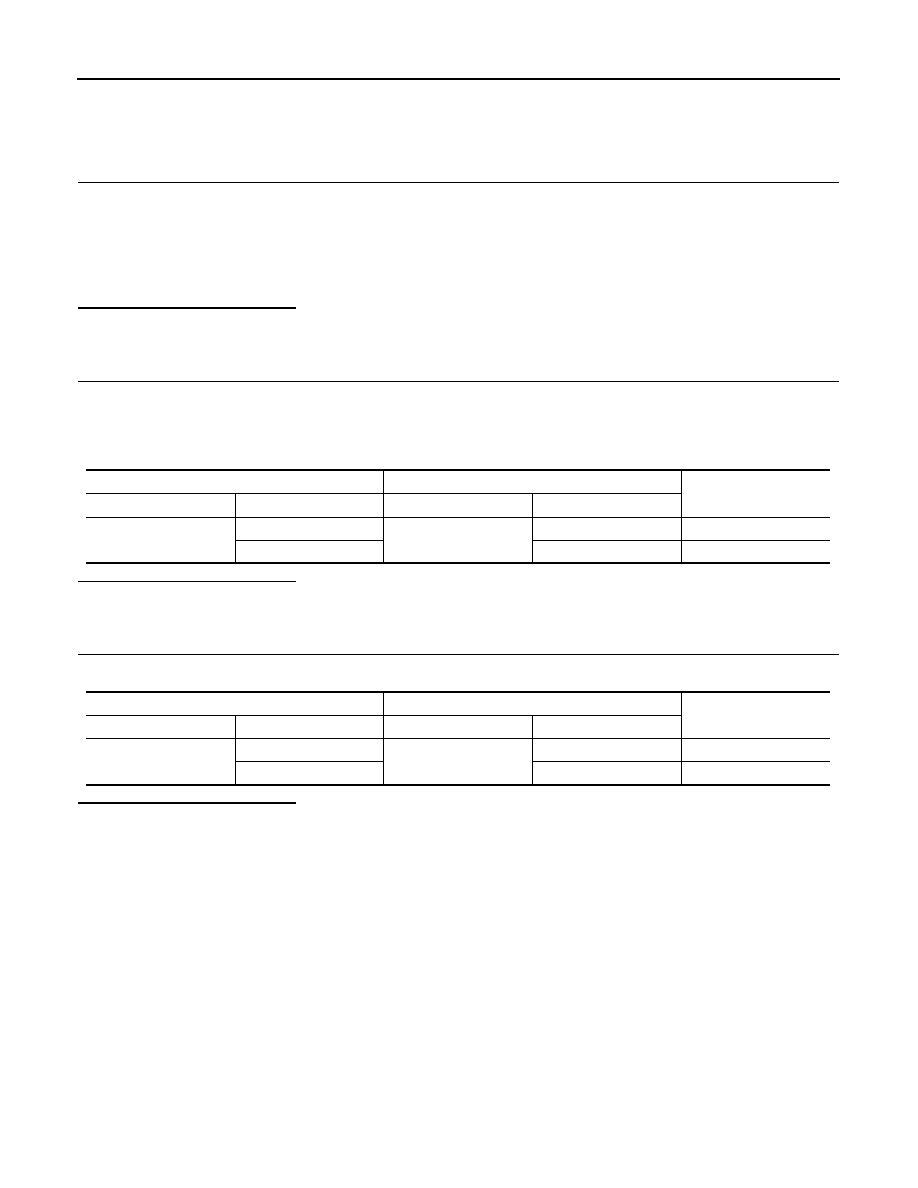
3.

CHECK HARNESS CONTINUITY (OPEN CIRCUIT)

Check the continuity between the harness connector and the data link connector.

Is the inspection result normal?

YES (Present error)>>Check CAN system type decision again.
YES (Past error)>>Error was detected in the main line between the IPDM E/R and the data link connector. 
NO

>> Repair the main line between the harness connector M77 and the data link connector.

IPDM E/R harness connector

Harness connector

Continuity

Connector No.

Terminal No.

Connector No.

Terminal No.

E12

30

E105

40

Existed

28

41

Existed

Harness connector

Data link connector

Continuity

Connector No.

Terminal No.

Connector No.

Terminal No.

M77

40

M4

6

Existed

41

14

Existed

LAN

MAIN LINE BETWEEN DLC AND CCM CIRCUIT

LAN-73

< DTC/CIRCUIT DIAGNOSIS >

[CAN]

C

D

E

F

G

H

I

J

K

L

B

A

O

P

N

MAIN LINE BETWEEN DLC AND CCM CIRCUIT

Diagnosis Procedure

INFOID:0000000010715316

1.

CHECK HARNESS CONTINUITY (OPEN CIRCUIT)

1.

Turn the ignition switch OFF.

2.

Disconnect the battery cable from the negative terminal.

3.

Disconnect the following harness connectors.

-

ECM

-

Chassis control module

4.

Check the continuity between the data link connector and the chassis control module harness connector.

Is the inspection result normal?

YES (Present error)>>Check CAN system type decision again.
YES (Past error)>>Error was detected in the main line between the data link connector and the chassis con-

trol module.

NO

>> Repair the main line between the data link connector and the chassis control module.

Data link connector

Chassis control module harness connector

Continuity

Connector No.

Terminal No.

Connector No.

Terminal No.

M4

6

M73

4

Existed

14

3

Existed

LAN-74

< DTC/CIRCUIT DIAGNOSIS >

[CAN]

MAIN LINE BETWEEN CCM AND 4WD CIRCUIT

MAIN LINE BETWEEN CCM AND 4WD CIRCUIT

Diagnosis Procedure

INFOID:0000000010715317

1.

CHECK CONNECTOR

1.

Turn the ignition switch OFF.

2.

Disconnect the battery cable from the negative terminal.

3.

Check the following terminals and connectors for damage, bend and loose connection (connector side
and harness side).

-

Harness connector M13

-

Harness connector B3

Is the inspection result normal?

YES

>> GO TO 2.

NO

>> Repair the terminal and connector.

2.

CHECK HARNESS CONTINUITY (OPEN CIRCUIT)

1.

Disconnect the following harness connectors.

-

Chassis control module

-

Harness connectors M13 and B3

2.

Check the continuity between the chassis control module harness connector and the harness connector.

Is the inspection result normal?

YES

>> GO TO 3.

NO

>> Repair the main line between the chassis control module and the harness connector M13.

3.

CHECK HARNESS CONTINUITY (OPEN CIRCUIT)

1.

Disconnect the connector of 4WD control unit.

2.

Check the continuity between the harness connector and the 4WD control unit harness connector.

Is the inspection result normal?

YES (Present error)>>Check CAN system type decision again.
YES (Past error)>>Error was detected in the main line between the chassis control module and the 4WD

control unit. 

NO

>> Repair the main line between the harness connector B3 and the 4WD control unit.

Chassis control module harness connector

Harness connector

Continuity

Connector No.

Terminal No.

Connector No.

Terminal No.

M73

4

M13

25

Existed

3

24

Existed

Harness connector

4WD control unit harness connector

Continuity

Connector No.

Terminal No.

Connector No.

Terminal No.

B3

25

B5

8

Existed

24

16

Existed

LAN

MAIN LINE BETWEEN CCM AND PWBD CIRCUIT

LAN-75

< DTC/CIRCUIT DIAGNOSIS >

[CAN]

C

D

E

F

G

H

I

J

K

L

B

A

O

P

N

MAIN LINE BETWEEN CCM AND PWBD CIRCUIT

Diagnosis Procedure

INFOID:0000000011009329

1.

CHECK CONNECTOR

1.

Turn the ignition switch OFF.

2.

Disconnect the battery cable from the negative terminal.

3.

Check the following terminals and connectors for damage, bend and loose connection (connector side
and harness side).

-

Harness connector M13

-

Harness connector B3

Is the inspection result normal?

YES

>> GO TO 2.

NO

>> Repair the terminal and connector.

2.

CHECK HARNESS CONTINUITY (OPEN CIRCUIT)

1.

Disconnect the following harness connectors.

-

Chassis control module

-

Harness connectors M13 and B3

2.

Check the continuity between the chassis control module harness connector and the harness connector.

Is the inspection result normal?

YES

>> GO TO 3.

NO

>> Repair the main line between the chassis control module and the harness connector M13.

3.

CHECK HARNESS CONTINUITY (OPEN CIRCUIT)

1.

Disconnect the connector of automatic back door control unit.

2.

Check the continuity between the harness connector and the automatic back door control unit harness
connector.

Is the inspection result normal?

YES (Present error)>>Check CAN system type decision again.
YES (Past error)>>Error was detected in the main line between the chassis control module and the auto-

matic back door control unit. 

NO

>> Repair the main line between the harness connector B3 and the automatic back door control unit.

Chassis control module harness connector

Harness connector

Continuity

Connector No.

Terminal No.

Connector No.

Terminal No.

M73

4

M13

25

Existed

3

24

Existed

Harness connector

Automatic back door control unit harness connector

Continuity

Connector No.

Terminal No.

Connector No.

Terminal No.

B3

25

B24

24

Existed

24

12

Existed


содержание   ..  1506  1507  1508  1509   ..