содержание .. 145 146 147 148 ..
Nissan X-Trail 32. Manual - part 147
BRC-54
< SYSTEM DESCRIPTION >
[WITH VDC (ESP)]
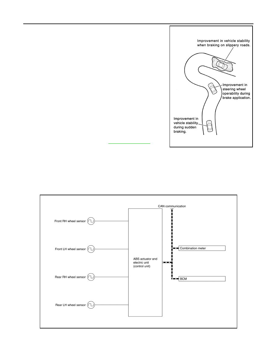
SYSTEM
• The following effects are obtained by preventing wheel lock during
braking.
- Vehicle tail slip is prevented during braking when driving straight.
- Understeer and oversteer tendencies are moderated during brak-
ing driving on a corner.
- Obstacles may be easily bypassed by steering operation during
braking.
• CONSULT can be used to diagnose the system diagnosis.
• Fail-safe function is adopted. When a malfunction occurs in ABS
function, the control is suspended for VDC function, TCS function,
ABS function, brake limited slip differential (BLSD) function, brake
assist function, brake force distribution function, hill start assist
function, advanced hill descent control function (4WD models with
gasoline engine), active trace control function (control of chassis
control module) and active ride control function (control of chassis
control module). The vehicle status becomes the same as models
without VDC function, TCS function, ABS function, brake limited
slip differential (BLSD) function, brake assist function, brake force
distribution function, hill start assist function, advanced hill descent
control function (4WD models with gasoline engine), active trace
control function (control of chassis control module) and active ride
control function (control of chassis control module). However, EBD
function is operated normally. Refer to
.
NOTE:
• ABS function has the characteristic as described here, This is not the device that helps reckless driving.
• To stop vehicle efficiently, ABS does not operate and ordinary brake operates at low speed [approx. 10 km/h
(6 MPH) or less, but differs subject to road conditions).
• Self-diagnosis is performed immediately after when engine starts and when vehicle initially is driven [by vehi-
cle speed approx. 15 km/h (9 MPH)]. Motor sounds are generated during self-diagnosis. In addition, brake
pedal may be felt heavy when depressing brake pedal lightly. These symptoms are not malfunctions.
SYSTEM DIAGRAM
INPUT SIGNAL AND OUTPUT SIGNAL
Major signal transmission between each unit via communication lines is shown in the following table.
JPFIC0140GB
JSFIA2368GB