содержание .. 139 140 141 142 ..
Nissan X-Trail 32. Manual - part 141
BRC-30
< SYSTEM DESCRIPTION >
[WITH VDC (ESP)]
SYSTEM
SYSTEM
System Description
INFOID:0000000010723631
• The system switches fluid pressure of each brake to increase, to hold or to decrease according to signals
from control unit in ABS actuator and electric unit (control unit). This control system is applied to VDC func-
tion, TCS function, ABS function, EBD function, brake limited slip differential (BLSD) function, brake assist
function, brake force distribution function, hill start assist function and advanced hill descent control function
(4WD models with gasoline engine).
• Fail-safe function is available for each function and is activated by each function when system malfunction
occurs.
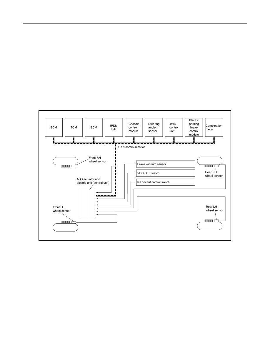
SYSTEM DIAGRAM
NOTE:
• 4WD control unit is applied to 4WD models.
• TCM is applied to CVT models.
• hill descent control switch is applied to 4WD models with gasoline engine.
INPUT SIGNAL AND OUTRET SIGNAL
Major signal transmission between each unit via communication lines is shown in the following table.
JSFIA2365GB