Nissan X-Trail 32. Manual - part 1408


  Главная      Nissan     Nissan X-Trail 32 - Service Manual


поиск по сайту            


содержание   ..  1406  1407  1408  1409   ..


Nissan X-Trail 32. Manual - part 1408


BLOWER MOTOR

HAC-107

< DTC/CIRCUIT DIAGNOSIS >

[AUTOMATIC AIR CONDITIONING]

C

D

E

F

G

H

J

K

L

M

A

B

HAC

N

O

P

BLOWER MOTOR

Diagnosis Procedure

INFOID:0000000010939764

1.

CHECK FUSE

1.

Turn ignition switch OFF.

2.

Check following fuses.

-

15 A fuse [Nos. 17 and 27, located in fuse block (J/B)]

NOTE:
Refer to 

PG-84, "Fuse, Connector and Terminal Arrangement"

.

Is the inspection result normal?

YES

>> GO TO 2.

NO

>> Replace the blown fuse after repairing the affected circuit if a fuse is blown.

2.

CHECKPOWER TRANSISTOR POWER SUPPLY

1.

Disconnect power transistor connector. 

2.

Turn ignition switch ON.

3.

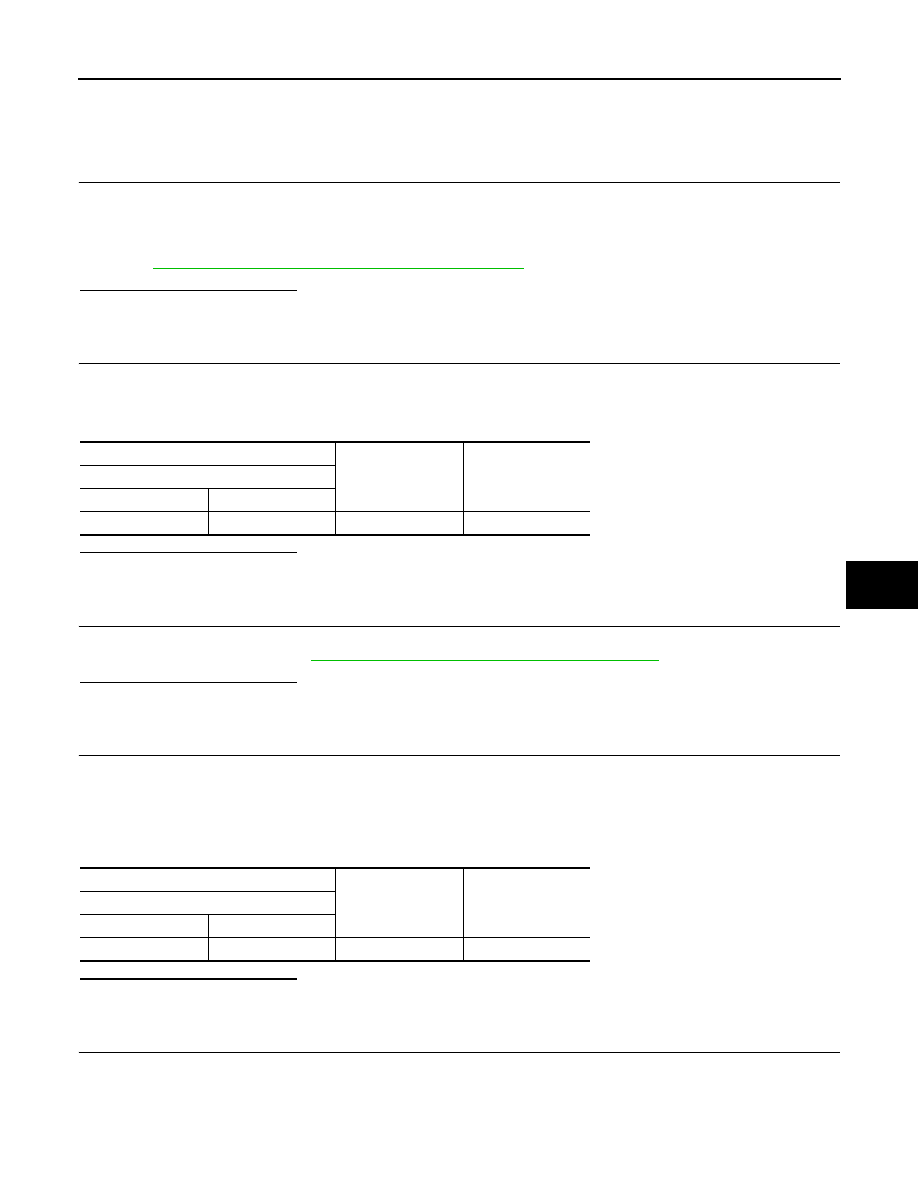
Check voltage between power transistor harness connector and ground. 

Is the inspection result normal?

YES

>> GO TO 4.

NO

>> GO TO 3.

3.

CHECK BLOWER RELAY

1.

Turn ignition switch OFF.

2.

Check blower relay. Refer to 

HAC-110, "Component Inspection (Blower Relay)"

.

Is the inspection result normal?

YES

>> Repair harness or connector between power transistor and fuse.

NO

>> Replace blower relay.

4.

CHECK BLOWER MOTOR CONTROL CIRCUIT

1.

Turn ignition switch OFF.

2.

Connect power transistor connector. 

3.

Disconnect blower motor connector. 

4.

Turn ignition switch ON.

5.

Check voltage between blower motor harness connector and ground. 

Is the inspection result normal?

YES

>> GO TO 6.

NO

>> GO TO 5.

5.

CHECK BLOWER MOTOR CONTROL CIRCUIT FOR OPEN

1.

Turn ignition switch OFF.

2.

Disconnect power transistor connector.

3.

Check continuity between power transistor harness connector and blower motor harness connector. 

+

Voltage

Power transistor

Connector

Terminal

M349

4

Ground

Battery voltage

+

Voltage

Blower motor

Connector

Terminal

M347

1

Ground

Battery voltage

HAC-108

< DTC/CIRCUIT DIAGNOSIS >

[AUTOMATIC AIR CONDITIONING]

BLOWER MOTOR

Is the inspection result normal?

YES

>> Replace power transistor. Refer to 

HAC-133, "Removal and Installation"

.

NO

>> Repair harness or connector.

6.

CHECK BLOWER MOTOR GROUND CIRCUIT

1.

Turn ignition switch OFF.

2.

Disconnect power transistor connector.

3.

Check continuity between power transistor harness connector and blower motor harness connector. 

Is the inspection result normal?

YES

>> GO TO 7.

NO

>> Repair harness or connector.

7.

CHECK POWER TRANSISTOR GROUND CIRCUIT

Check continuity between power transistor harness connector and ground. 

Is the inspection result normal?

YES

>> GO TO 8.

NO

>> Repair harness or connector.

8.

CHECK POWER TRANSISTOR CONTROL SIGNAL

1.

Connect power transistor connector and A/C auto amp. connector. 

2.

Turn ignition switch ON.

3.

Set air outlet to VENT. 

4.

Change fan speed from 1st – 7th, and check duty ratios between power transistor harness connector and
ground by using an oscilloscope. 
NOTE:
Calculate the drive signal duty ratio as shown in the figure.
T2 = Approx. 2.5 ms

Is the inspection result normal?

Power transistor

Blower motor

Continuity

Connector

Terminal

Connector

Terminal

M350

5

M347

1

Existed

Power transistor

Blower motor

Continuity

Connector

Terminal

Connector

Terminal

M350

6

M347

2

Existed

Power transistor

Continuity

Connector

Terminal

M349

2

Ground

Existed

+

Condition

Duty ratio

(Approx.)

Voltage

Power transistor

Connector

Terminal

Fan speed (manual) Air 

outlet: VENT

M349

1

Ground

1st

21%

2nd

24%

3rd

31%

4th

40%

5th

54%

6th

70%

7th

100%

JPIIA1646GB

BLOWER MOTOR

HAC-109

< DTC/CIRCUIT DIAGNOSIS >

[AUTOMATIC AIR CONDITIONING]

C

D

E

F

G

H

J

K

L

M

A

B

HAC

N

O

P

YES

>> GO TO 10.

NO

>> GO TO 9.

9.

CHECK POWER TRANSISTOR CONTROL SIGNAL CIRCUIT FOR OPEN

1.

Turn ignition switch OFF.

2.

Disconnect power transistor connector and A/C auto amp. connector.

3.

Check continuity between power transistor harness connector and A/C auto amp. harness connector. 

Is the inspection result normal?

YES

>> Replace A/C auto amp. Refer to 

HAC-126, "Removal and Installation"

.

NO

>> Repair harness or connector.

10.

CHECK BLOWER MOTOR FEEDBACK SIGNAL

When fan speed is set to OFF, and check voltage between power transistor harness connector and ground. 

Is the inspection result normal?

YES

>> GO TO 12.

NO

>> GO TO 11.

11.

CHECK BLOWER MOTOR FEEDBACK SIGNAL CIRCUIT FOR OPEN

1.

Turn ignition switch OFF.

2.

Disconnect power transistor connector and A/C auto amp. connector.

3.

Check continuity between power transistor harness connector and A/C auto amp. harness connector. 

Is the inspection result normal?

YES

>> Replace A/C auto amp. Refer to 

HAC-126, "Removal and Installation"

.

NO

>> Repair harness or connector.

12.

REPLACE POWER TRANSISTOR

1.

Turn ignition switch OFF.

2.

Replace power transistor. Refer to 

HAC-133, "Removal and Installation"

.

3.

Turn ignition switch ON.

4.

Change fan speed from 1st – 7th, and check that blower motor operates normally. 

Is the inspection result normal?

YES

>> INSPECTION END

NO

>> Replace blower motor. Refer to 

VTL-15, "Removal and Installation"

.

Component Inspection (Blower Motor)

INFOID:0000000010939765

1.

CHECK BLOWER MOTOR-I

1.

Remove blower motor. Refer to 

VTL-15, "Removal and Installation"

.

2.

Check that there is not any mixing foreign object in the blower motor. 

Is the inspection result normal?

YES

>> GO TO 2.

Power transistor

A/C auto amp.

Continuity

Connector

Terminal

Connector

Terminal

M349

3

M173

27

Existed

+

Voltage

Power transistor

Connector

Terminal

M349

1

Ground

11 - 14 V

Power transistor

A/C auto amp.

Continuity

Connector

Terminal

Connector

Terminal

M349

1

M173

37

Existed

HAC-110

< DTC/CIRCUIT DIAGNOSIS >

[AUTOMATIC AIR CONDITIONING]

BLOWER MOTOR

NO

>> Replace blower motor. Refer to 

VTL-15, "Removal and Installation"

.

2.

CHECK BLOWER MOTOR-II

Check that there is not breakage or damage in the blower motor. 

Is the inspection result normal?

YES

>> GO TO 3.

NO

>> Replace blower motor. Refer to 

VTL-15, "Removal and Installation"

.

3.

CHECK BLOWER MOTOR-III

Check that blower motor turns smoothly. 
Is the inspection result normal?

YES

>> INSPECTION END

NO

>> Replace blower motor. Refer to 

VTL-15, "Removal and Installation"

.

Component Inspection (Blower Relay)

INFOID:0000000010939766

1.

CHECK BLOWER RELAY

1.

Remove blower relay. Refer to 

PG-84, "Fuse, Connector and Terminal Arrangement"

2.

Check continuity between blower relay terminal 3 and 5 when
the voltage is supplied between terminal 1 and 2. 

Is the inspection result normal?

YES

>> INSPECTION END

NO

>> Replace blower relay.

Terminal

Voltage

Continuity

3

5

ON

Existed

OFF

Not existed

JSIIA1551ZZ


содержание   ..  1406  1407  1408  1409   ..